Traditional Bridge Mode
Using VLAN-aware bridges on your switch is recommended. Use traditional mode bridges only if you need to run more than one bridge on the switch or if you need to use PVSTP+.
Create a Traditional Mode Bridge
You can configure a traditional mode bridge either using
NCLU
or manually editing the /etc/network/interfaces file.
Configure a Traditional Bridge with NCLU
NCLU has limited support for configuring bridges in traditional mode.
The traditional bridge must be named something other than bridge, as that name is reserved for the single VLAN-aware bridge that you can configure on the switch.
The following example shows how to create a simple traditional mode bridge configuration on the switch, including adding the switch ports that are members of the bridge. You can choose to add one or more of the following elements to the configuration:
-
You can add an IP address to provide IP access to the bridge interface.
-
You can use glob syntax to specify a range of interfaces.
-
You can set two STP attributes on the bridge ports: portautoedge and portrestrole.
The portautoedge attribute defaults to yes; to use a setting other than the default, you must set this attribute to no. The portrestrrole attribute defaults to no, but to use a setting other than the default, you must specify this attribute without setting an option.
The defaults for these attributes do not appear in the NCLU configuration.
To configure a traditional mode bridge using NCLU, do the following:
cumulus@switch:~$ net add bridge my_bridge_A ports swp1-4
cumulus@switch:~$ net add bridge my_bridge_A ip address 10.10.10.10/24
cumulus@switch:~$ net add interface swp1 stp portautoedge no
cumulus@switch:~$ net add interface swp2 stp portrestrrole
cumulus@switch:~$ net pending
cumulus@switch:~$ net commit
These commands create the following configuration snippet in the
/etc/network/interfaces file:
cumulus@switch:~$ cat /etc/network/interfaces

...

auto swp1
iface swp1
    mstpctl-portautoedge no

auto swp2
iface swp2
    mstpctl-portrestrrole yes

auto swp3
iface swp3

auto swp4
iface swp4

...
auto my_bridge_A
iface my_bridge_A
    address 10.10.10.10/24
    bridge-ports swp1 swp2 swp3 swp4
    bridge-vlan-aware no
Verify the configuration by running net show config commands:
cumulus@switch:~$ net show config commands
...
net add bridge my_bridge_A ip address 10.10.10.10/24
net add bridge my_bridge_A ports swp1,swp2,swp3,swp4
...
net add interface swp1 stp portautoedge no
net add interface swp2 stp portrestrrole
...
Manually Configure a Traditional Mode Bridge
To create a traditional mode bridge manually, you need to hand edit the
/etc/network/interfaces file:
-
Open the
/etc/network/interfacesfile in a text editor. -
Add a new stanza to create the bridge, and save the file. The example below creates a bridge with STP enabled and the MAC address ageing timer configured to a lower value than the default:
 auto my_bridge
 iface my_bridge
     bridge-ports bond0 swp5 swp6
     bridge-ageing 150
     bridge-stp on
Configuration Option
Description
Default Value
bridge-ports
List of logical and physical ports belonging to the logical bridge.
N/A
bridge-ageing
Maximum amount of time before a MAC addresses learned on the bridge expires from the bridge MAC cache.
1800 seconds
bridge-stp
Enables spanning tree protocol on this bridge. The default spanning tree mode is Per VLAN Rapid Spanning Tree Protocol (PVRST).
For more information on spanning-tree configurations see Spanning Tree and Rapid Spanning Tree.
off
The name of the bridge must be compliant with Linux interface naming conventions and unique within the switch.
Do not try to bridge the management port, eth0, with any switch ports (like swp0, swp1, and so forth). For example, if you created a bridge with eth0 and swp1, it will not work.
-
Reload the network configuration using the
ifreloadcommand:cumulus@switch:~$ sudo ifreload -a
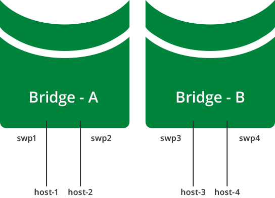
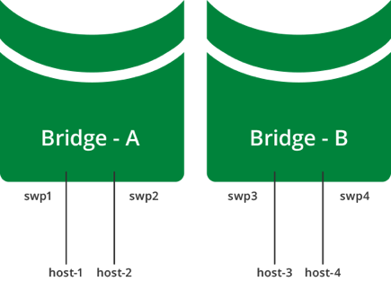
You can configure multiple bridges, in order to logically divide a switch into multiple layer 2 domains. This allows for hosts to communicate with other hosts in the same domain, while separating them from hosts in other domains.
The diagram below shows a multiple bridge configuration, where host-1 and host-2 are connected to bridge-A, while host-3 and host-4 are connected to bridge-B. This means that:
- host-1 and host-2 can communicate with each other.
- host-3 and host-4 can communicate with each other.
- host-1 and host-2 cannot communicate with host-3 and host-4.

This example configuration looks like this in the
/etc/network/interfaces file:
auto bridge-A
iface bridge-A
    bridge-ports swp1 swp2
    bridge-stp on

auto bridge-B
iface bridge-B
    bridge-ports swp3 swp4
    bridge-stp on
Trunks in Traditional Bridge Mode
The IEEE standard for trunking is 802.1Q. The 802.1Q specification adds a 4 byte header within the Ethernet frame that identifies the VLAN of which the frame is a member.
802.1Q also identifies an untagged frame as belonging to the native VLAN (most network devices default their native VLAN to 1). The concept of native, non-native, tagged or untagged has generated confusion due to mixed terminology and vendor-specific implementations. Some clarification is in order:
- A trunk port is a switch port configured to send and receive 802.1Q tagged frames.
- A switch sending an untagged (bare Ethernet) frame on a trunk port is sending from the native VLAN defined on the trunk port.
- A switch sending a tagged frame on a trunk port is sending to the VLAN identified by the 802.1Q tag.
- A switch receiving an untagged (bare Ethernet) frame on a trunk port places that frame in the native VLAN defined on the trunk port.
- A switch receiving a tagged frame on a trunk port places that frame in the VLAN identified by the 802.1Q tag.
A bridge in traditional mode has no concept of trunks, just tagged or untagged frames. With a trunk of 200 VLANs, there would need to be 199 bridges, each containing a tagged physical interface, and one bridge containing the native untagged VLAN. See the examples below for more information.
The interaction of tagged and un-tagged frames on the same trunk often leads to undesired and unexpected behavior. A switch that uses VLAN 1 for the native VLAN may send frames to a switch that uses VLAN 2 for the native VLAN, thus merging those two VLANs and their spanning tree state.
Trunk Example

To create the above example:
cumulus@switch:~$ net add bridge br-VLAN100 ports swp1.100,swp2.100
cumulus@switch:~$ net add bridge br-VLAN200 ports swp1.200,swp2.200
cumulus@switch:~$ net pending
cumulus@switch:~$ net commit
These commands create the following configuration snippet in the /etc/network/interfaces file:
auto br-VLAN100
iface br-VLAN100
    bridge-ports swp1.100 swp2.100
    bridge-stp on

auto br-VLAN200
iface br-VLAN200
    bridge-ports swp1.200 swp2.200
    bridge-stp on
VLAN Tagging Examples
You can find more examples of VLAN tagging in the VLAN tagging chapter.
Caveats
On Broadcom switches, when two VLAN subinterfaces are bridged to each
other in a traditional mode bridge, switchd does not assign an
internal resource ID to the subinterface, which is expected for each
VLAN subinterface.
To work around this issue, add a VXLAN on the bridge so that it does not require a real tunnel IP address.