Custom Topology (Legacy)
The information on this page reflects the workflows for the legacy Air UI, which is being deprecated. View documentation for the new UI
NVIDIA Air fully supports the creation of custom topologies. This feature augments the pre-built demo infrastructure.
To access custom topologies, click the Build Your Own card on the Create a Simulation page:
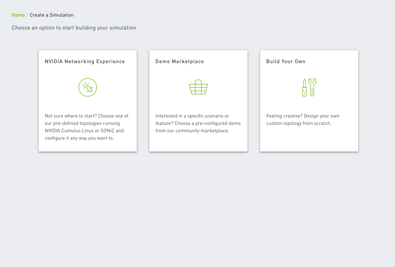
You can also click the air.nvidia.com/build link.
Custom Topology Landing Page
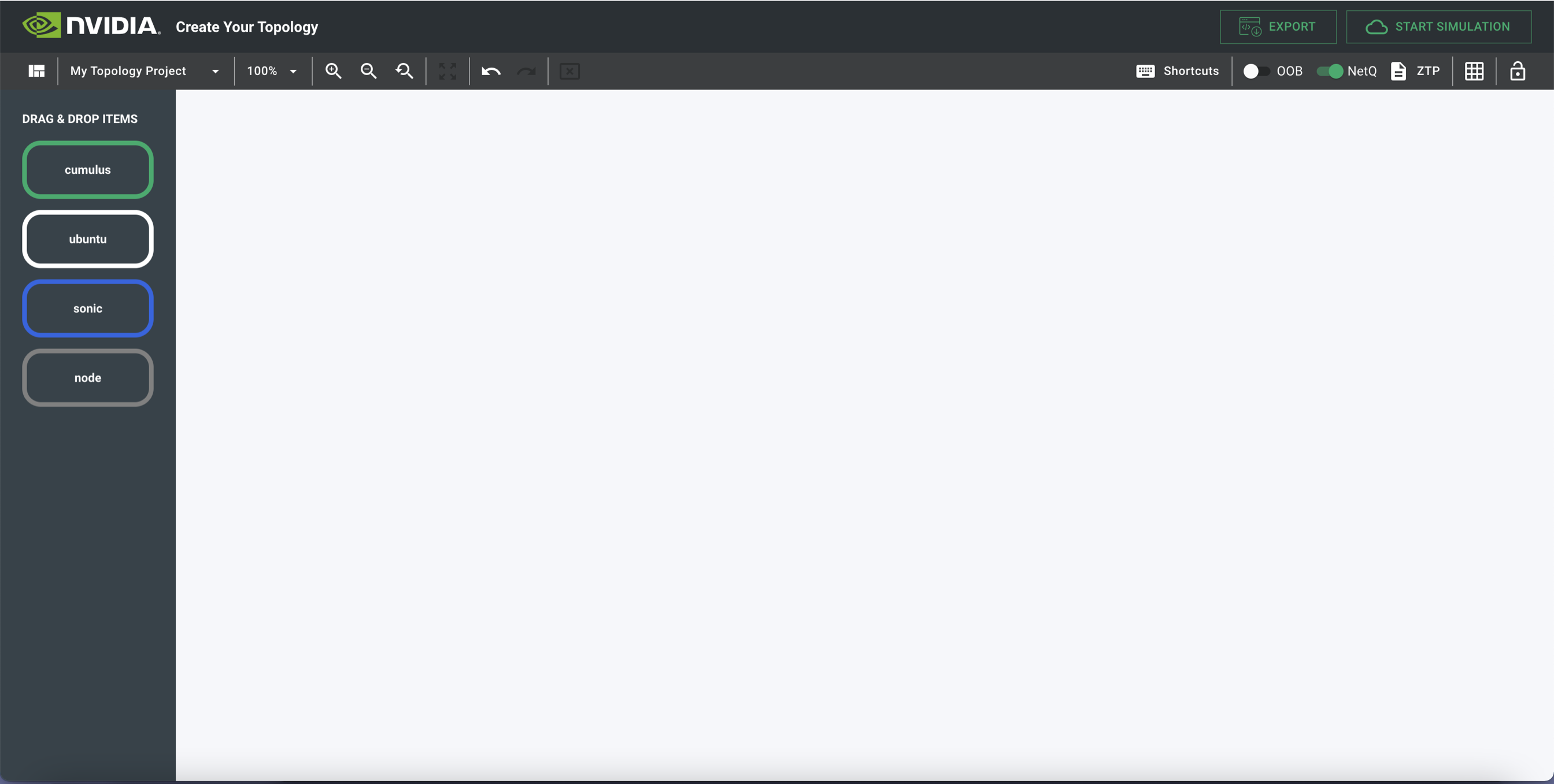
The custom topology landing page is a blank canvas that you can use to design any network.
Canvas Overview
The left panel lists the nodes you can use to create the custom topology:
- Cumulus VX switches
- Ubuntu servers
- SONiC switches
- Generic nodes
The toolbar at the top of the custom topology landing page manages the topology. Click the default name My Topology Project for additional management options.
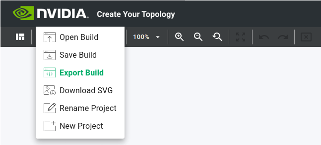
- Open Build uploads a JSON-structured custom topology build. This is not the same as importing a
topology.dotGraphviz format document. The JSON format structure is unique to the custom topology builder tool. - Save Build exports a JSON-structured custom topology that represents the canvas. Only use the custom topology builder application to read and interpret this JSON file; do not open and edit the file in a text editor.
- Export Build exports the topology as a Graphviz format
topology.dotfile. You can import this file into the NVIDIA Air simulation platform to launch a custom topology. - Download SVG downloads an image in SVG format that defines your topology.
- Rename Project renames the project.
- New Project creates a new project.
Add Nodes
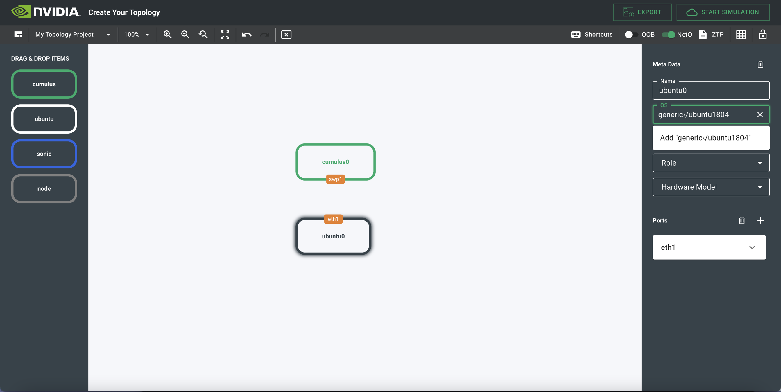
To add a node, drag and drop it from the left panel.
Edit Nodes
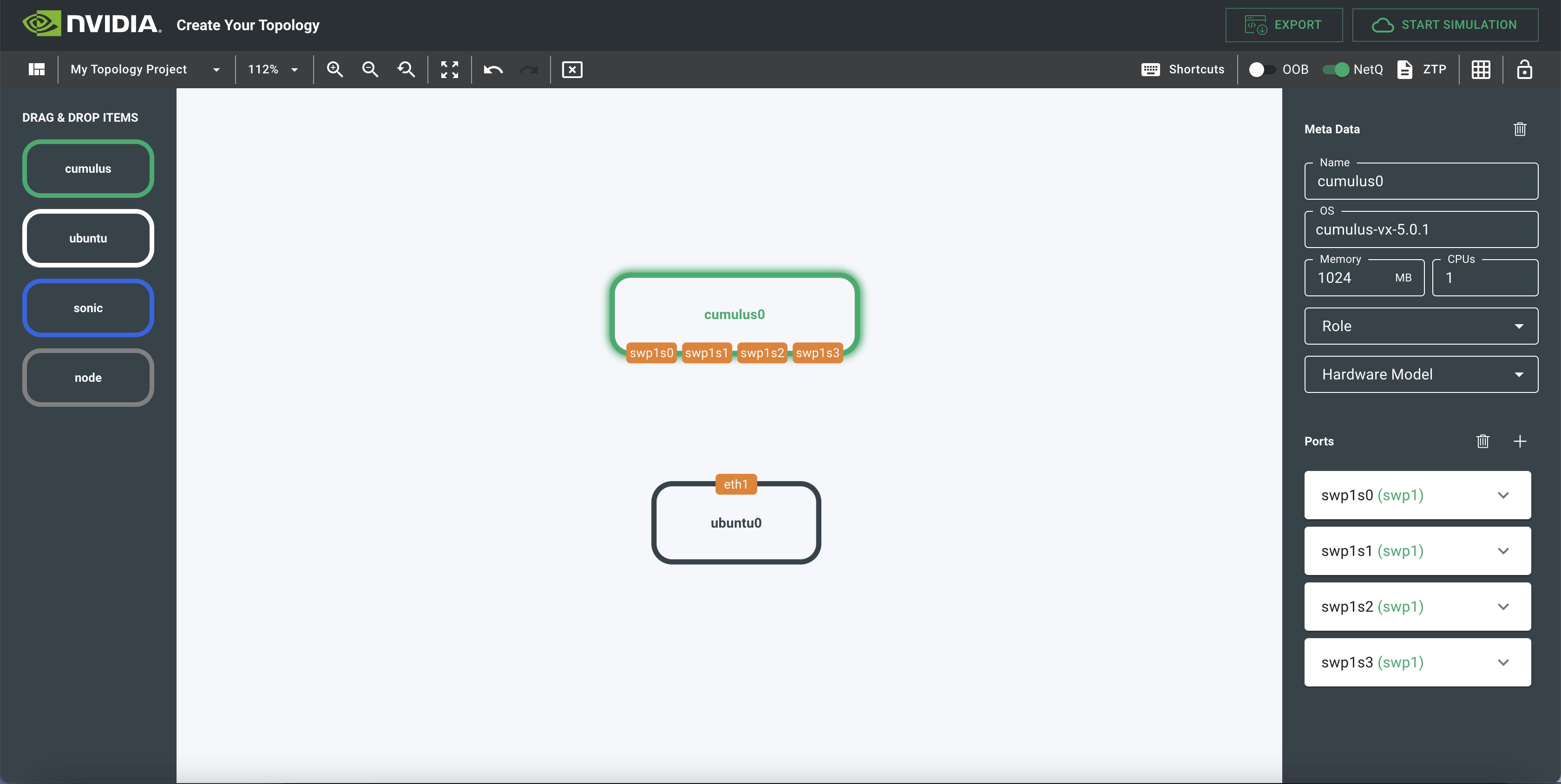
After you add a node, you can edit it as needed. Click the node to select it and configure it using the options in the right panel.
-
Name is the hostname of the node.
-
OS is the operating system version on the node. The supported operating system versions are in a dropdown list.
-
Memory is the amount of RAM on the node. The default is 1GB.
-
CPU is the number of CPUs allocated to the node. The default is 1 CPU.
-
Role is an advanced feature that defines the role of the node to affect boot order. You typically do not have to assign a role.
-
Hardware Model pre-populates the ports based on a specific hardware model of the switch you select. This does not affect the simulation but acts as a macro to pre-populate the number of ports per switch model.
-
Ports adds, renames, and edits port location and information for the diagram. Press the breakout button (<-||->) to simulate breaking out a port into a group of four.
Connect Nodes
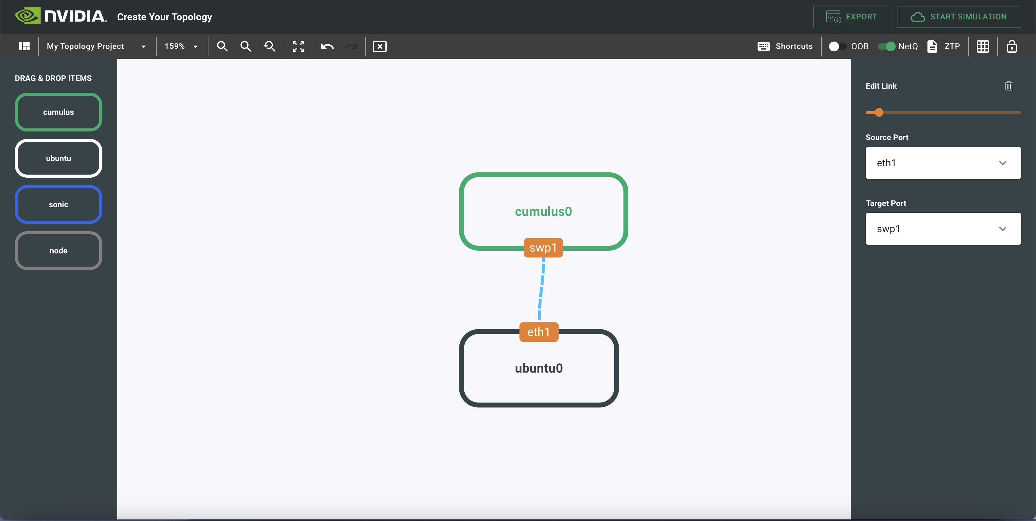
To connect two nodes together, click a port on one node and drag it to the port on the other node. This draws a line between the two ports to show the connection.
ZTP Script
You can include a custom ZTP script as part of the network design. When you create the simulation, NVIDIA Air copies the ZTP script, exactly as pasted into the text field, onto the oob-mgmt-server. Any network node making a ZTP request on the OOB management network has access to this ZTP script through a DHCP server and web server running on the oob-mgmt-server.
To upload a ZTP script, click ZTP in the top right of the canvas:

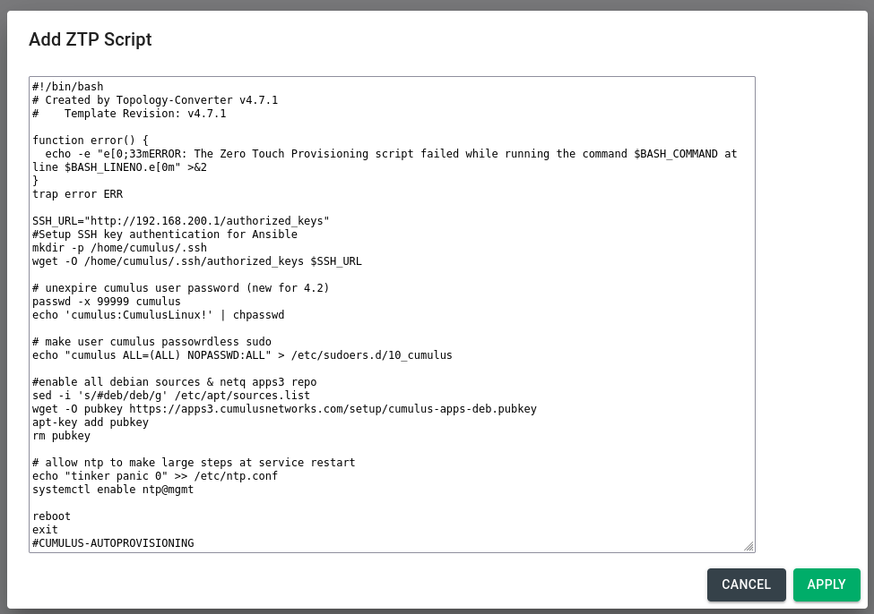
A popup window opens where you can paste the contents of the ZTP script. The popup window contains a default script. The default script is a guide to implement common ZTP features on Cumulus Linux, such as:
- Disable password expiry
- Make the
cumulususer passwordless forsudo - Download SSH keys for key based SSH
After you apply the ZTP script, ZTP in the top right of the canvas changes color from grey to green, indicating that ZTP is now active on your oob-mgmt-server.

Build a Custom Topology
To build a custom topology, you can either:
- Start a simulation directly from the topology builder.
- Export the topology files and upload them directly into NVIDIA Air.

Start a Simulation Directly
To start a simulation directly from the topology builder, click the START SIMULATION button. The simulation starts and redirects you to the NVIDIA Air landing page. The topology and the diagram link automatically to your simulation.
Export a Custom Topology
To export a custom topology, click the EXPORT button to download two files:
topology.dotis the network definition in Graphviz format.topology.svgis the network diagram in Scalable Vector Graphics format.
To upload the topology.dot and topology.svg files:
-
In the sidebar, click Create a Simulation to open the Create a Simulation window.
-
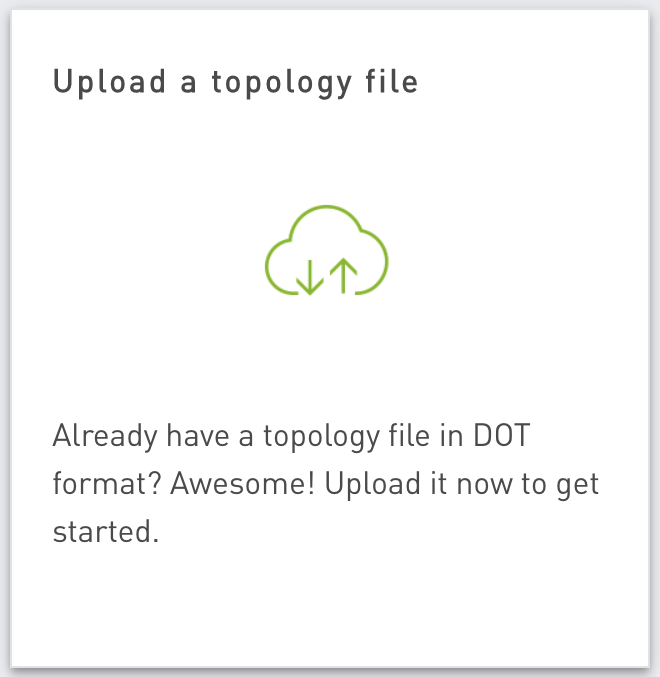
Click Build Your Own, then click Upload a topology file.
-
Drag the
topology.dotfile onto the Drop a topology file here card and thetopology.svgfile onto the Drop a diagram file here card, then click SUBMIT.
NetQ Integration
To include NetQ with any simulation, make sure the NetQ toggle switch is on, which is the default behavior.

To disable NetQ, click the toggle switch to disable it.
Create a Custom Topology from the Production Network
This section describes how to create a simulation based on an existing production deployment.
Gather cl-support from the Production Network
Use these playbooks to gather the cl-support script output. The ReadMe in the repository provides instructions on how to run the playbook to gather the cl-support output.
Create topology.dot from the Production Network
After you obtain the cl-support output, you can create a topology.dot file with this script. You can run the script using python3. Here is sample output:
$ python3 cl_support_lldp_parser.py
Extracting: /home/cumulus/cl_support_lldp_parser/cl_support_leaf01_20210721_164553.txz
Extracting: /home/cumulus/cl_support_lldp_parser/cl_support_spine02_20210721_164553.txz
Extracting: /home/cumulus/cl_support_lldp_parser/cl_support_leaf02_20210721_164553.txz
Extracting: /home/cumulus/cl_support_lldp_parser/cl_support_spine01_20210721_084129.txz
folder is: /home/cumulus/cl_support_lldp_parser/cl_support_leaf01_20210721_164553
leaf01
    leaf01:eth0 -- oob-mgmt-switch:swp2
    leaf01:swp31 -- spine01:swp1
    leaf01:swp32 -- spine02:swp1
folder is: /home/cumulus/cl_support_lldp_parser/cl_support_spine02_20210721_164553
spine02
    spine02:eth0 -- oob-mgmt-switch:swp6
    spine02:swp1 -- leaf01:swp32
    spine02:swp2 -- leaf02:swp32
folder is: /home/cumulus/cl_support_lldp_parser/cl_support_leaf02_20210721_164553
leaf02
    leaf02:eth0 -- oob-mgmt-switch:swp4
    leaf02:swp31 -- spine01:swp2
    leaf02:swp32 -- spine02:swp2
folder is: /home/cumulus/cl_support_lldp_parser/cl_support_spine01_20210721_084129
spine01
    spine01:eth0 -- oob-mgmt-switch:swp5
    spine01:swp1 -- leaf01:swp31
    spine01:swp2 -- leaf02:swp31
DOTFILE: cl_support_lldp_parser.dot
The command writes the output to cl_support_lldp_parser.dot. You need to manually edit this file to define the node versions and clean up any superfluous configurations:
$ cat cl_support_lldp_parser.dot
graph dc1 {
"leaf01" [function="leaf" ]
"oob-mgmt-switch" [function="leaf" ]
"spine01" [function="leaf" ]
"spine02" [function="leaf" ]
"leaf02" [function="leaf" ]
    "leaf01":"eth0" -- "oob-mgmt-switch":"swp2"
    "leaf01":"swp31" -- "spine01":"swp1"
    "leaf01":"swp32" -- "spine02":"swp1"
    "spine02":"eth0" -- "oob-mgmt-switch":"swp6"
    "spine02":"swp2" -- "leaf02":"swp32"
    "leaf02":"eth0" -- "oob-mgmt-switch":"swp4"
    "leaf02":"swp31" -- "spine01":"swp2"
    "spine01":"eth0" -- "oob-mgmt-switch":"swp5"
}
Restore Configuration Files
After you create the simulation, you can restore the configuration files.
This python script pulls out all the relevant files and collates them into folders so you can use them to restore configuration from inside the simulation.
You can also use the infrastructure as code Ansible playbook to restore configurations.