Campus Architecture Solution Guide
NVIDIA, with the potent combination of the Cumulus Linux network operating system and the Cumulus NetQ real-time visibility and telemetry platform, brings the proven success of open and disaggregated networking from the data center into campus networks. The NVIDIA vision of open standards driving open networking hardware with software disaggregation creates powerful opportunities to significantly reduce both CapEx and OpEx and streamline network operations.
This guide walks a network architect or administrator through the various technology options, design considerations and recommended choices for building a highly available modern campus network.
Cumulus Linux Network Operating System
Cumulus Linux is the industry-leading open network operating system (NOS) that drives open networking switches built on commodity hardware and switching silicon. It is the key that brings the same hardware and software disaggregation advantages to the network that IT departments already enjoy for their application servers and storage resources.
Incumbent and traditional networking vendors create lock-in by bundling a proprietary operating system on custom built and proprietary networking hardware. Open networking switches often contain the same hardware forwarding chipsets as traditional vendors. When you need to run Linux on a server today, you have your choice of any bare metal server from any manufacturer that meets your needs and budget. The commitment to the operating system is a separate choice from the hardware that it runs on.
Cumulus Linux is an open, native Linux distribution that allows for choice in hardware to provide a wide range of speeds, feeds and features. By being an open NOS, administrators have maximum hardware and application choice. You can easily reuse the same monitoring and operational tools already in use for Linux systems in the enterprise today to operate and monitor the network infrastructure.
Cumulus Linux is fully featured networking software providing the entire suite of enterprise networking features, including:
- Layer 2 spanning tree protocol
- Layer 1 diagnostics with TDR
- Layer 3 OSPF, BGP and multicast
- VXLAN and BGP-EVPN
- TACACS, LDAP and RADIUS authentication
- 802.1X interfaces with change of authorization (CoA)
- Port security
- SNMPv2c/v3
- NCLU, a full network CLI with tab completion, built-in documentation and commit/rollback
Because Cumulus Linux is a full Linux distribution based on Debian, administrators have the full power of a Linux system at their fingertips. This provides the ability to run containers or on-system agents for functions like streaming telemetry via NetQ, Telegraf or Prometheus or native automation support for tools like Ansible, Saltstack or Puppet.
Cumulus Hardware Partners
Cumulus Linux runs on over 100 open switch platforms from more than 10 hardware manufacturers, providing the widest choice and ultimate control over supply chain, procurement, speeds and features. Networking hardware from multiple vendors can become unified and simple to operate with Cumulus Linux running as a standard NOS. Cumulus Linux supports the widest range of platforms in the industry from open hardware vendors and is now extending this freedom and choice to the modern campus.
Cumulus NetQ Streaming Telemetry Platform
Built using the same open, modern, web-scale principals that inspires Cumulus Linux, Cumulus NetQ is a highly scalable, modern network operations toolset that provides unprecedented visibility to your network operations in real time. By design, Cumulus NetQ can process large amounts of data to deliver realtime insights and perform complex networkwide troubleshooting and validation tasks at nearly any scale.
Adding Cumulus NetQ to a network powered by Cumulus Linux heightens visibility, eases troubleshooting, and enriches existing monitoring and operational strategies with an all-in-one tool that provides information such as:
- MLAG and bond status
- Port status
- MAC address locations and movement over time
- Network service health (BGP, OSPF, NTP and more)
- Layer 2 and layer 3 path tracing
- Network service and routing protocol validations
Cumulus NetQ provides a rich graphical UI, a command line interface, as well as a RESTful API to provide maximum flexibility to retrieve data about the real-time state of the entire network, and you can even go back in time.
In addition to monitoring Cumulus Linux network nodes, you can install Cumulus NetQ agents on other Linux servers to extend visibility out to beyond the edge of the network. Cumulus NetQ agents monitor the Linux kernel and stream timestamped event and health data to a telemetry server either on premises or in the cloud. With this system-wide, timestamped telemetry, Cumulus NetQ delivers rich analytics and verifications, even against historical data points in the past, providing another dimension to troubleshooting and operations capabilities. You can install the Cumulus NetQ agent on bare metal Linux hosts or inside Linux VMs.
The Cumulus NetQ agent currently supports:
- Cumulus Linux 3.3.0 and later
- Ubuntu 16.04 and 18.04
- Red Hat Enterprise Linux (RHEL) 7.1
- CentOS 7
The Cumulus NetQ agent streams all the data it collects to the Cumulus NetQ appliance. This appliance is available as either a bare metal appliance from NVIDIA or as a virtual appliance for use on nearly any hypervisor.
Campus Networks Overview
Traditionally, a campus network refers to the portion of a network architecture that delivers connectivity to end users and connected devices across a single geographic location. The size and other physical characteristics of the single geographic location can vary significantly. A campus network can be a single floor, wing, building or cluster of buildings. You build campus networks by connecting groups of smaller LANs over small physical areas.
The enterprise that owns the campus network normally owns and manages the physical wires and data infrastructure. Often, these physical characteristics guide and constrain design and architecture options in addition to business and application requirements. As a matter of practice, campus networks usually aim to build the fastest functional network that the physical infrastructure can support.
Enterprise IT is consistently under pressure to reduce costs while maintaining a highly available infrastructure to drive business functions. Automation of the network and its operations is proving to be the most useful strategy to deliver a range of benefits. The momentum of automation and its success in data centers and cloud environments are creating new opportunities for similar CapEx and OpEx reductions throughout the rest of the enterprise. Those that take advantage of automation enjoy benefits such as:
- Reduced human error: Test and verify changes and updates before programmatically deploying them. This eliminates typos and procedural errors to reduce overall risk.
- Increased uptime: Make fewer impacting errors as a result of fewer manual operations. Deploy programmatic changes more quickly and using less time, especially at scale.
- Increased agility: More rapid deployments allow for more frequent changes based on user demand and business needs.
- Improved monitoring and management: Use automation tools to improve and customize monitoring and management to suit nearly any use case or requirement.
- Advanced troubleshooting: Flexibly collect any information for any problem as often as needed.
- Operational efficiency: Network operators can manage larger numbers of network devices. Shift resources to address other technical debt or on higher value tasks.
Automation is revolutionizing and more fully enabling the networking industry. By providing the full and untethered power of Linux to its users, Cumulus Linux is the original “automation first” network operating system, allowing you to manage your network nodes as if they were any other Linux server.
Principles of Campus Network Design
As you plan your network designs and architectures, it is important to consider emerging networking trends and future needs of the enterprise. Several dimensions influence and guide campus design, such as:
- Future growth and scalability: You can design networks in ways today that can have significant impact on how they grow and scale. Making a small design concession in the spirit of scalability is often a wise choice even if future plans are clear.
- Existing infrastructure: Copper cables can only reach 10Gbps on Cat 6 cable. Cat 5e can support more than 1Gbps. Features like 802.3bz can use existing copper to achieve more than 1Gbps.
- Security and segmentation: Regulatory compliance and security best practices can create many design challenges for isolation and controlling traffic flows. Consider these decisions early in the design phase.
- Cost: Budgetary requirements drive several matters of choice. Redundancy is often at odds with cost.
- Bandwidth needs and oversubscription: Understanding high level traffic flows for applications deployed in a local area of the campus can create the need for higher speed or additional links between devices in the topology.
- Operations and management: What is it like to use and manage the devices that form the network infrastructure? How quickly and easily can you make changes? How easy is it to monitor the devices and how easy is it to troubleshoot when things go wrong?
Hierarchy and modularity are the basis for the structure of the campus network. Like all complex systems, you design, build and grow networks as discrete sets of smaller building blocks. This allows for flexibility and customization depending on needs local to the users or business applications in that area and the ability to scale or expand by adding additional building blocks. A hierarchy allows for each layer or tier to specialize and optimize for its unique role.
Classically, a campus network hierarchy has three tiers:
- Core
- Distribution (Aggregation)
- Access
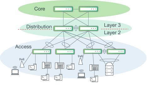
Three-tiered hierarchical model
The three-tiered model is useful for understanding the distinct roles of network devices to provide a framework to customize and tailor for your own most effective use. In practice, there are no absolute rules that govern how a campus network must be physically built. Many larger campus networks are constructed with three distinct tiers, while a smaller network may find enough overlap and cost savings in the distribution and core tier functions that they can be collapsed into a single tier. A hierarchical design describes each tier’s unique set of functions, services and specific role in the design.
Core Tier
In large and multi-site campus environments, where there are multiple sets of distribution layer switches, a core layer is often used as an interconnection. The chief design goals for the core layer are based on delivering a nonstop forwarding service and ensuring there is an appropriate level of redundancy to provide seamless failover in the event of a failure of any component. The core must also be designed to allow for the occasional hardware or software upgrade or change without disrupting enterprise applications.
These design requirements drive a very simple and reliable design built on layer 3 routed point-to-point links. The core should not implement any complex policy services such as load balancers and firewalls, nor should it provide any direct user or device access. Connectivity into the core from the distribution layer and connections between core nodes is layer 3 only. A strictly layer 3 core allows for the elimination of layer 2 control plane protocols such as MLAG and spanning tree and affords a much simpler, reliable and scalable core.
Distribution (Aggregation) Tier
The distribution layer has a unique role by serving as a boundary between the access and core layers. A critical function of the distribution layer is segmenting the network to contain disruptions and changes to a smaller area. It supports a number of important services that fall outside of the highly specialized goals of the access and core layers. First, this layer serves as the aggregation point for all of the access switches in a segment of the campus. Often, routing, firewalls, load balancing, and other policy-based enforcement services occur in the distribution layer. It plays a role in the core layer routing design, acting as a summarization and redistribution point.
A discrete distribution layer is usually required for sites with more than a few access layer switches. It quickly becomes impractical to interconnect all access switches together directly, compared to aggregating at a distribution layer. The configuration and platform choice in this layer are often driven by requirements in the access and core layers and the needs of other network and policy implementation services such as wireless or security.
Access Tier
The access layer is the edge of the wired network and is where end user devices are attached to gain connectivity to the rest of the campus. Some devices attached at the access layer create a micro-extension beyond an access switch’s physical port. Devices such as wireless access points and IP phones are two notable examples that provide small extensions to the access layer.
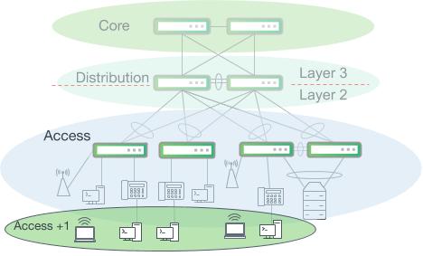
Wireless clients and workstations behind IP phones are not directly connected to access switch ports
The wide variety of devices that connect to the access layer, along with the large security attack surface, requires the access layer to be one of the most feature rich parts of the campus network. It provides security, QoS, device discovery and even physical infrastructure services like power over Ethernet.
Building Campus Networks
Segmentation
Designing a high speed, highly available and scalable network requires careful attention to many important details, which are covered in this guide. Attention to detail becomes increasingly challenging as the size of the campus network grows. To optimize design for local needs and as a means to be thorough and deliberate, modularizing or compartmentalizing a campus network is usually required when there is more than a handful of network devices in the topology.
Logically segmenting or dividing a network into sections is not always straightforward with clear boundaries. Many portions of the network rely on each other to function properly, so boundaries can be difficult to determine, especially when considering physical geography and proximity. The logical segment boundaries do not necessarily have to fall perfectly along the lines of the three-tier hierarchy model. There are no absolute rules that govern how a particular campus should be segmented. Below are some examples of common divisions of campus networks.
Core
Sharing a name with and also mapping to the hierarchical model tier, the core is the layer 3 backbone that interconnects the other segments of the campus network. A dedicated core segment consists of at least two nodes that are distinctly different from the layer 3 devices that terminate a WAN or service provider connection. Not all campus networks require a dedicated core.
The core segment optimizes for speed, simplicity and high availability. There may not be any native layer 2 extension into or across the core. As will be discussed in a later section, overlay networks and tunneling protocols such as VXLAN are now the de facto solution to extend layer 2 connectivity across layer 3 boundaries such as a campus core.
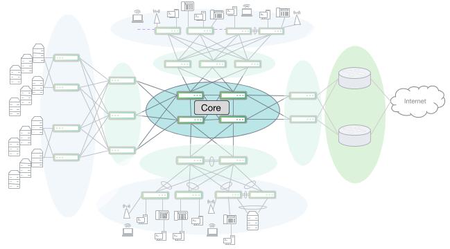
A campus core network interconnecting several other campus segments, including a large server room
Aggregation and Access
This is the most familiar segment of a campus network. This includes the access and distribution layers of the traditional three-tiered hierarchical model. For large scale design, often with multiple buildings and multiple sets of distribution layer switches, it is useful to logically group a distribution switch and all of its southbound devices as a logical unit connected to the core.
Different aggregation & access segments can be designed differently to meet local device and user needs. Some business applications create much more east-west traffic (within a segment) versus north-south traffic (in and out of the network segment) which may drive the need for higher speeds or higher numbers of uplinks from the access layer.
High port density deployments may take advantage of breakout or fan-out cabling at the distribution layer to support extremely large numbers of access switches. For example, a 32x100G Trident3 based switch can have each 100G port split into 4x25G. This can allow for support of up to 128x25G ports or up to 128 switches to be interconnected. With access switches each having 48 ports x 128 switches, this example can provide 6144 access ports for end device connectivity.1
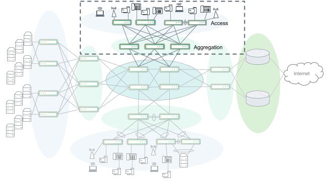
An access and aggregation block
Depending on each use case, services such as security, wireless and VoIP may be implemented inside of this segment, but can also warrant their own logical segmentation depending on size and complexity.
Services
Some designs may require a set of enterprise network applications and services that, with enough scale or with unique enough requirements, are best suited as their own segment. A call center, for example, may require a large number of voice gateway and call processing nodes along with tight security compliance requirements for payment processing or patient health records.
A fully-featured enterprise campus may include wireless controllers, security appliances, voice and video services, server load balancers, identity and access control services, video surveillance and more. Depending on the geography and deployment models of these services, it can be useful to centralize them into a logical network segment of their own to be able to optimize platform and design choices.
Data Center or Server Racks
Some campus networks provide connectivity into a data center, server room or a set of server racks. Like other specialized segments, the connectivity requirements and needs of data centers and servers drive different platform and feature choices. Depending on the size and use case, a data center may connect to a distribution layer or directly into the core.
Data center networks are designed to accommodate high volumes of east-west traffic and optimize for speed, low latency and high availability. Data centers and server rooms with more than one rack are normally built using a leaf/spine or Clos style design. The close proximity of racks provides for minimal impact with increased cabling complexity.
Clos or leaf/spine-style network segments. Large server rooms with two or more full racks should deploy a leaf/spine network design.
WAN/Edge
Almost all campus networks have a connection to a WAN of some form. Similar to the data center, a WAN/edge segment has unique requirements that drive specific platform and feature choices. Circuit speed changes from the LAN to the WAN create the need for rich QoS with deep buffering capabilities to smooth out bursty traffic flows. Serving as the demarcation and handoff from a service provider can drive the need for features such as MPLS or may require large hardware forwarding table sizes to accommodate internet routing tables.
A WAN/edge segment may also include dedicated security appliances to perform the first layer of policy enforcement and monitoring. VPN and tunneling services are often implemented here to connect geographically disparate sites together or provide remote access for field and remote workers. The WAN/edge section may also include a DMZ (demilitarized zone) to help quarantine necessary inbound public internet traffic.
Design Considerations
Collapsing or Consolidating Layers
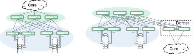
In cases where the network is contained to a single floor or even with multiple adjacent buildings and a sufficient number of fiber runs, it is possible to collapse the core into distribution switches as shown in the figure below.
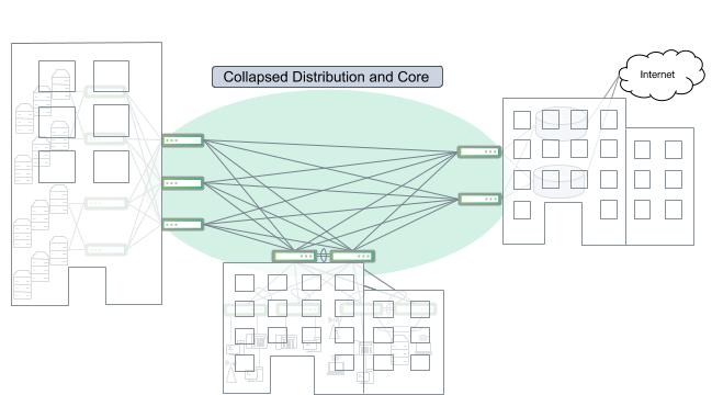
A cluster of buildings with interconnected distribution switches and no dedicated core layer
Similarly, it may be possible in some instances such as a very small building or sparse connectivity needs to combine the access and distribution layers into a single switch or pair of switches and route directly into a core layer.
A large campus network with collapsed distribution and access segments that route directly into the layer 3 core
Layer 2 vs Layer 3 ECMP Device Connections
Often, application or business requirements create a need for layer 2 (VLAN) adjacency between endpoints. VLANs are used to group together devices that are in the same geographic area and have similar network service and policy enforcement needs. Switches use layer 2 links (trunks) to extend layer 2 connectivity to other devices across the network. At reasonably small scales, this works well with little reason for concern.
VLAN extension can become problematic with large numbers of switches or when a layer 2 adjacency needs to span a wide geographic area. A layer 2 segment is a shared failure domain, and the behaviors of spanning tree can lead to network brownouts, or temporary periods of reduced bandwidth or increased latency. The nature of broadcast domains and shared trunk links exposes a risk that loops or storms in one VLAN may affect all other VLANs on those trunks.
In addition, layer 2 networks running spanning tree result in topology changes or failures in one area having ripple effects, triggering reconvergence across the entire domain. This reconvergence can cause temporary traffic outages as spanning tree blocks ports to prevent loops. Plus, in large layer 2 networks MAC address tables are larger, especially at the distribution layer, and as a result, hardware ASIC limits may need to be closely monitored. Further, scaling a distribution layer beyond two switches becomes particularly difficult for spanning tree to reliably converge quickly. Most layer 2 designs rely heavily on proprietary MLAG protocols to form layer 2 trunks to a pair of switches. This dependency creates the undesirable side effects of increasing control plane complexity, introducing an additional point of failure and another dimension of vendor lock-in.
By contrast, interconnecting network devices using layer 3 routed equal cost multipath (ECMP) links provides a few distinct advantages over layer 2 trunks. By keeping layer 2 broadcast domains smaller, spanning tree scale and convergence issues are kept in check. In some campus network designs, routing can occur at the access layer switches. This removes the need for uplinks into the distribution to be layer 2 bonds. What follows is a reduction or elimination of MLAG as a control plane dependency and the peer links or inter-switch links that are required to support the pairing. Additionally, since distribution layer switches only perform layer 3 routing in this design, it addresses many of the layer 2 (MAC address) hardware table size concerns.
The emergence of EVPN for VXLAN enables network architects and designers to realize the benefits of a layer 3 ECMP network while still providing layer 2 extension across the campus. The section below on EVPN and VXLAN discusses more details about how to achieve layer 2 extension over a layer 3 network to achieve the best of both layer 2 and layer 3.
BGP Unnumbered
BGP Unnumbered is a Cumulus Linux feature that comprises two major tasks for configuring BGP, which drastically reduce configuration complexity and ease deployment.
Traditionally, when configuring BGP between two devices, an IPv4 address is needed to serve as the binding point for the session. For large numbers of point-to-point layer 3 links, like in a core, it can be burdensome to allocate and manage internal IPv4 subnet space for large numbers of point-to-point links.
The IPv6 standard prescribes that all IPv6-enabled interfaces automatically generate and assign a link local IPv6 address in the fe80::/10 address space. BGP Unnumbered takes advantage of this feature and eliminates the need to configure any IPv4 addresses on routed links for BGP.
The other major problem that BGP Unnumbered solves is that traditionally, BGP configuration requires an explicit peer IP address to be configured. This is the address that the BGP peer will open a TCP socket to, for BGP session establishment. BGP Unnumbered also solves this problem by listening for IPv6 router advertisements and dynamically building a BGP session to the IPv6 link local address in the router advertisement that it receives from its peer on the other side of the point-to-point link.
Another important component, RFC5549, provides for IPv4 routes to be advertised with IPv6 next hops. This enables an IPv6 network, even one built entirely out of automatically generated link local addresses, to be able to advertise IPv4 reachability from end to end without a need for IPv4 address assignment.
Because of this, BGP is much simpler to configure. Instead of requiring a peer address for each BGP neighbor, we can refer to the physical interface identifier and only need to specify if it is an internal (iBGP) neighbor or an external (eBGP) neighbor. This makes building and configuring a layer 3 routed network nearly plug and play.
For more information on BGP Unnumbered and eBGP inside the network, download the free ebook here: https://www.nvidia.com/en-us/networking/border-gateway-protocol/
EVPN and VXLAN
EVPN as a control plane for VXLAN has emerged from the data center as an ideal solution to provide the best of both layer 2 and layer 3 designs. Network designers and architects are beginning to apply the proven successes of building a mostly layer 3 routed network using BGP Unnumbered then applying EVPN and VXLAN to provide VLAN extension and layer 2 connectivity to anywhere in the campus it is required.
The key benefit of VXLAN is that layer 2 VLANs can be extended over a layer 3 routed network. This provides many of the same VLAN and MAC mobility benefits that drive layer 2 designs, while allowing for the network infrastructure to inherit the reliability and scale benefits of a routed layer 3 design.
While MAC address learning and move (mobility) convergence for EVPN with VXLAN is fast and satisfactory for most enterprise applications, use cases that require seamless mobility with nonstop packet forwarding across an entire layer 2 domain cannot currently be satisfied with a BGP EVPN-controlled VXLAN topology.
EVPN is an extension to the BGP routing protocol and natively supports multi-tenancy with VRFs. Using BGP to manage routing for the layer 3 network and also EVPN for VXLAN further reduces operational complexity by using the same control plane protocol to drive the entire network.
VXLAN is an encapsulation protocol that tunnels Ethernet frames between network endpoints over layer 3 IP networks. A network device that performs VXLAN encapsulation/decapsulation for the network is referred to as a VTEP (VXLAN tunnel endpoint). When a VTEP sends a frame into a VXLAN tunnel, it wraps the original frame in a VXLAN header that includes the VNI (virtual network identifier). The VNI maps to the original VLAN that the packet belongs to at the ingress switch. After applying a VXLAN header, it is encapsulated into a UDP/IP packet for transmission to another VTEP over an IP network.
When the VXLAN packet arrives at the remote VTEP, it reads the VNI from the VXLAN header. The VNI identifies which VLAN or interface the tunneled frame should be processed on after stripping off and discarding the VXLAN/UDP/IP encapsulation. After decapsulation and reclassification to an interface by the VNI, the original Ethernet frame is able to be bridged or routed again as if it were a regular inbound packet.
Multi-tenancy
Multi-tenancy is the concept that describes the logical separation of the network inside of shared network devices and across shared links. Isolation is achieved in a multi-tenant network by the use of VLANs at layer 2 and VRF (virtual routing and forwarding) for layer 3. BGP EVPN natively carries VRF specific, IP prefix routes. It is possible to achieve granular isolation and traffic control in several different ways.
The ideal multi-tenancy solution depends mostly on the size and scale of each tenant and the network architecture. Small networks built with layer 2 links are usually able to achieve isolation by using simple layer 2 VLANs. Isolation is enforced at the layer 3 boundary, or default gateway, where policy and security enforcement can take place.
In most traditional multi-tenancy deployments a policy device like a firewall isolates security zones, but this requires two subnets within the same security zone to still traverse the policy device, either creating a need for a larger firewall or limiting throughput of intra-zone traffic.
When using a layer 3 network, VRFs provide isolation by keeping IP traffic between two VRFs entirely isolated from each other. VRFs implement an entirely different and independent routing and IP forwarding table in the Linux kernel. Routing between VRFs is achieved through route leaking or by forwarding traffic through VRF-unaware paths. As a result, two hosts in different subnets but still within the same policy zone can use their local top of rack switch as a default gateway and only traverse the firewall or policy device when crossing between security zones (VRFs).
To provide information about VRFs and tenant reachability throughout the network, BGP-EVPN is used as a control plane protocol between network devices. EVPN speakers exchange their list of locally configured VRFs as well as the associated hosts within that VRF. It is through this exchange that routing policy is learned and traffic can be either routed locally within a VRF or through a policy device between VRFs.
Switch Stacking
Stacking is the concept of combining multiple smaller switches together to operate and be managed as a single unit. On the surface, it provides a number of benefits, but like any other aspect of networking, carries a few tradeoffs. At the time when switch stacking was conceived, network operations were a very manual CLI process. As networks scaled, recurring operating expenses also increased with the need for more manual operators. In response, network vendors looked for ways to consolidate points of management. A switch stack is a means to that end.
In addition, most single hardware ASICs at the time were unable to deliver wire-speed performance on all ports with a single chip. To achieve the required port density and attain wire speed forwarding on all ports, multiple ASICs had to be linked to create switch stacks and chassis. By contrast, commodity switching ASICs that power today’s open networking switches can support up to 128 ports on a single chip in a 1U form factor.
The other hidden risk in stacking is the complexity in the stacking management plane. This requires a highly complex and coordinated effort and state progression between the individual switches to join together and act as a single logical stack. This creates rigid constraints in platform choice since all switches in a stack must be from the same vendor, same model or family and usually the same code versions. Adding greater management plane complexity by implementing stacking is at odds with the broad goal of keeping management and control plane simple and reducing dependencies on proprietary protocols. Complex features tend to fail in complex and difficult to predict ways.
Automation tools such as Ansible, Saltstack and Puppet address the need to consolidate and reduce management points. Cloud scale operators are able to use automation to manage 40,000 servers with a single operator. Enterprises are noticing the success and impact of automation in their data centers and are applying these strategies into the rest of their campus networks.
Over time, switch stacks have become ingrained into legacy campus design. Being a modern network operating system and by following network design philosophies and principles that we believe are best, Cumulus Linux does not support switch stacking. In instances where switch stacks currently exist or are being considered, multiple 1U devices acting as standalone devices can be used to provide the connectivity that a switch stack would offer.
The recommended designs in the section below illustrate how to build campus networks without needing to configure and group switches using stacking.
Chassis Switches
Similar to the concept of stacking, chassis switches have traditionally been a way to scale port density while maintaining a single point of device management. Chassis improve on a switch stack in a few minor ways, but tend to carry a higher cost. A chassis switch can also provide for embedded and on box services like security or wireless. Chassis switches tend to be used more often in the core and distribution layers while switch stacks tend to be used in the access layer.
Chassis create lock-in and a certain inflexibility of the network devices and services that it can support. Cards or blades are proprietary form factors, making it impossible to act as standalone devices. A chassis is usually a long term investment due to its high initial cost combined with the idea that components of the chassis can be upgraded as capabilities and speeds improve over time. This continues to drive lock-in and forces long term decisions in other adjacent areas such as operations and management.
Open networking switches are almost exclusively built in fixed and non-modular form factors and support a wide range of pluggables. The Recommended Designs section below illustrates how campus networks can be built at scale without the need for large port-dense chassis switches.
Recommended Designs
Small Office - Remote Office
Small campus network sites such as remote and satellite offices are often able to collapse all LAN switching functions into a single switch or single pair of switches. A dedicated WAN/edge router is required and security devices may also be implemented near the WAN edge depending on business and compliance needs.
For these small networks, inter-subnet routing can be performed on either the LAN switch or on a layer 3 device upstream. Performing routing upstream provides the opportunity for more robust and granular security and policy enforcement beyond what a LAN switch can provide in its hardware forwarding path, but may not be able to meet performance requirements. Inter-subnet routing can be performed at wire speed and takes the most direct path when performed on the LAN switch.
Platform choice is flexible and includes options with or without Power over Ethernet (PoE).
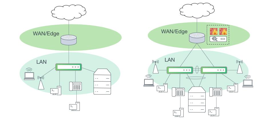
Small campus networks with consolidated network layers. Left: A small campus site with a single LAN switch. Right: One collapsed layer with one MLAG switch pair and security services in the WAN edge.
Single Site - Small Building
Campus networks that require more than two access switches also require a distribution layer. Interconnecting access switches in a mesh, ring or daisy chain fashion is not recommended. Access switches should be arranged in a hierarchy such that traffic between access switches flows through a distribution layer switch.
Exception: Two access switches configured as an MLAG pair with a peer link.
Connections between access layer and distribution layer switches can be built by using either layer 2 or layer 3 links. Designs using layer 2 links are usually selected if a VLAN must be extended beyond a single switch or MLAG pair, but EVPN and VXLAN discussed below should be considered to address this use case. At small scale, layer 2 designs are easy to configure and operate and are generally reliable.
However, most modern business applications do not require direct layer 2 adjacency. Enterprises without a need for native layer 2 extension across access switches and those that adopt EVPN and VXLAN are able to build a more reliable next generation campus network using layer 3 ECMP links.
This provides several key benefits:
- Spanning tree domains are limited to one or a pair of switches. Convergence and ripple effects of spanning tree are contained.
- Routing at the access layer enables a more efficient path for devices on the same switch.
- Distribution layer switches are not paired and do not run MLAG. The distribution layer can be more easily scaled out beyond a pair of switches.
NVIDIA recommends using eBGP Unnumbered to build and maintain the set of layer 3 links between the access and distribution switches. BGP Unnumbered uses auto-generated IPv6 link local addresses and several intuitive configuration optimizations to drastically reduce configuration and deployment complexity. For more information on eBGP Unnumbered, refer to the Cumulus Linux user guide.
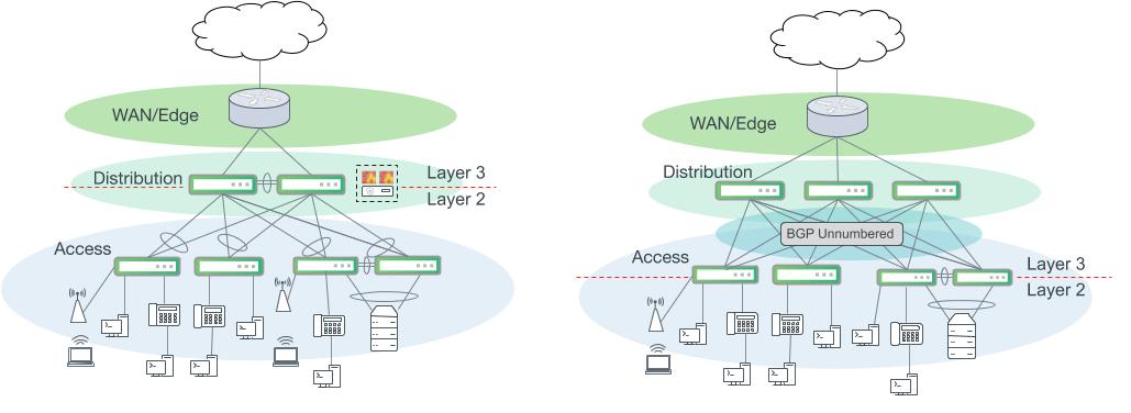
Campus networks with a distribution layer. Left: A classic campus network with layer 2 bonds interconnecting the access and distribution layer. Routing for access VLANs occurs at the distribution layer. Right: An alternative design using layer 3 ECMP uplinks from the access layer and BGP Unnumbered. Routing for access VLANs occurs at the access layer switches.
An optional improvement to the layer 3 ECMP design in the figure above includes an additional pair of switches to transition in and out of the broader aggregation and access network segment. Often, this serves as a multi-purpose services segment or block. This design option more closely adheres to Clos leaf/spine network design principles that have proven success in modern data centers.
In this configuration, distribution layer switches only route IP packets between access switches and participate in BGP to facilitate route advertisement. This simplicity has several inherent benefits. Troubleshooting is easier since we only need to examine routing and no switching operations. This also keeps the distribution layer configuration much simpler as there are no layer 2 control plane protocols needed and all of the complexity of route filtering, summarization or redistribution into another routing protocol for this segment occurs on the border switches.
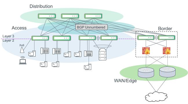
Layer 3 ECMP design with optional border switches.
| Tier | Supported Platforms |
|---|---|
| Distribution | Any Broadcom Trident3, Trident II+ or Mellanox Spectrum-based platform is preferred. Broadcom Tomahawk family is acceptable. |
| Border | Any Broadcom Trident3, Trident II+ or Mellanox Spectrum-based platform is preferred. Broadcom Tomahawk family is acceptable. |
Redistribute Neighbor
The Cumulus Linux layer 3 Redistribute Neighbor feature helps modernise your campus network to make it more resilient, maximize utilisation, and eliminate the use of the Spanning Tree Protocol (STP).
Redistribute neighbor provides a way for IP subnets to span racks without forcing the end hosts to run a routing protocol by redistributing the Address Resolution Protocol (ARP) table (Linux IP neighbor table) into a dynamic routing protocol, such as OSPF or BGP. The host routes continue to be advertised into the routing domain as /32 prefix routes. Routing protocols can achieve reachability by routing on the Longest Prefix Match (LPM) based on these /32 host routes.
Benefits
Using Redistribute neighbor provides the following benefits:
- Eliminates the requirement to stretch a layer 2 domain across the entire campus network or across more than one switch. Limiting your layer 2 domain between the access switch port and the directly-connected host eliminates STP from the entire network. Without a stretched layer 2 domain, BUM traffic is limited to the access switch port, where the host is directly connected.
- Provides faster convergence, greater resiliency, and packet forwarding intelligence because the multiple uplink ports on the access switch and the rest of the core network become layer 3. In addition, using Equal Cost Multipath (ECMP) on all layer 3 links lets you take advantage of the full available bandwidth. Coupling with features, such as BFD, helps you achieve essential sub-second failover and forwarding reconvergence on the core layer 3 links.
- Ensures efficiency, IP address conservation, and reduces IP address management by using BGP unnumbered interfaces for all layer 3 routing protocol links. Using BGP in the core enables you to achieve traffic engineering with route maps and prefix lists to manipulate routing and forwarding paths with the BGP attributes for certain prefixes and hosts.
- Optimises performance with the use of subnets. For example, when you have multiple buildings across the campus, you can allocate a /24 IP address block to a building, then another separate IP address block of /24 network addresses to another building, and so on. You can then perform route summarisation at the egress links of the building aggregation switches to summarise the subset /32 network prefixes and networks when advertising to the network core.
Example Configuration
The following example shows a core network fabric connected to building A. The design closely reflects a multi data center spine and leaf fabric design where there is a spine and leaf fabric for the network core and for each building:
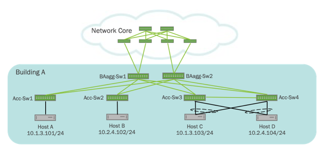
In the above example:
- Four hosts (Host A, Host B, Host C, and Host D) are connected to four separate access switches (Acc-Sw1, Acc-Sw2, Acc-Sw3, and Acc-Sw4). The access switches can be inside a closet or connecting hosts on a floor.
- The access switches then aggregate with separate layer 3 links to aggregation switches (BAagg-Sw1 and BAagg-Sw2) with BGP unnumbered running between them. These aggregation switches aggregate to a core spine and leaf fabric.
The routing configuration for the access switches (Acc-Sw1 and Acc-Sw3) is shown here:
cumulus@Acc-Sw1:mgmt-vrf:~# net show configuration commands
net add bgp autonomous-system 65011
net add routing import-table 10 route-map REDIST_NEIGHBOR
net add routing route-map LOOPBACK_ROUTES permit 10 match interface lo
net add routing route-map REDIST_NEIGHBOR permit 10 match interface vlan13
net add bgp router-id 10.0.0.11
net add bgp bestpath as-path multipath-relax
net add bgp neighbor swp19 interface remote-as external
net add bgp neighbor swp20 interface remote-as external
net add bgp neighbor peerlink.4094 interface remote-as internal
net add bgp ipv4 unicast redistribute connected route-map LOOPBACK_ROUTES
net add bgp ipv4 unicast redistribute table 10
cumulus@Acc-Sw3:mgmt-vrf:~# net show configuration commands
net add bgp autonomous-system 65013
net add bgp router-id 10.0.0.13
net add bgp bestpath as-path multipath-relax
net add bgp neighbor swp19 interface remote-as external
net add bgp neighbor swp20 interface remote-as external
net add bgp neighbor peerlink.4094 interface remote-as internal
net add bgp ipv4 unicast redistribute connected route-map LOOPBACK_ROUTES
net add bgp ipv4 unicast redistribute table 10
To verify connectivity between Host A (10.1.3.101) and Host C (10.1.3.103), which are on the same subnet, run these commands:
cumulus@Host_A:~$ 10.1.3.103 show eth1
4: eth1: <BROADCAST,MULTICAST,UP,LOWER_UP> mtu 1500 qdisc pfifo_fast state UP group default qlen 1000
    link/ether 44:38:39:00:00:75 brd ff:ff:ff:ff:ff:ff
    inet 10.1.3.101/24 scope global eth1
       valid_lft forever preferred_lft forever
    inet6 fe80::4638:39ff:fe00:75/64 scope link
       valid_lft forever preferred_lft forever
cumulus@Host_C:~$ 10.1.3.101 show eth1
7: eth1: <BROADCAST,MULTICAST,MASTER,UP,LOWER_UP> mtu 9000 qdisc noqueue state UP group default qlen 1000
    link/ether 44:38:39:00:00:73 brd ff:ff:ff:ff:ff:ff
    inet 10.1.3.103/24 brd 10.1.3.255 scope global eth1
       valid_lft forever preferred_lft forever
    inet6 fe80::4638:39ff:fe00:73/64 scope link
       valid_lft forever preferred_lft forever
In this design, you configure Proxy ARP on the VLAN attached to the host so that the switch responds to all ARP requests when a host sends an ARP request to a system on its subnet.
If you have many switches and need the VLAN across all the switches, you can specify a unique IP address on all the SVIs in the subnet, or you can use the anycast gateway with VRR. To conserve IP addresses, repeat physical IP addresses on a switch or switch pair (if you use MLAG).
The IP neighbor table on the hosts and the switches looks like this:
cumulus@Host_A:~$ sudo ip neighbor show | grep 10.1.3.103
10.1.3.103 dev eth1 lladdr 44:39:39:ff:00:13 REACHABLE
cumulus@Host_C:~$ sudo ip neigh show | grep 10.1.3.101
10.1.3.101 dev uplink lladdr 44:38:39:00:00:74 REACHABLE
cumulus@Acc-Sw1:mgmt-vrf:~# sudo ip neigh show 10.1.3.101
10.1.3.101 dev vlan13 lladdr 44:38:39:00:00:75 REACHABLE
cumulus@Acc-Sw3:mgmt-vrf:~# sudo ip neigh show 10.1.3.103
10.1.3.103 dev vlan13 lladdr 44:38:39:00:00:73 REACHABLE
The routing table on the access and aggregation switches look like this:
cumulus@Acc-Sw1:mgmt-vrf:~# net show bgp 10.1.3.103
BGP routing table entry for 10.1.3.103/32
Paths: (2 available, best #2, table default)
  Advertised to non peer-group peers:
  BAagg-Sw1(swp19) BAagg-Sw2(swp20)
  65021 65013
    fe80::4638:39ff:fe00:4d from BAagg-Sw2(swp20) (10.0.0.22)
    (fe80::4638:39ff:fe00:4d) (used)
      Origin incomplete, valid, external, multipath
      AddPath ID: RX 0, TX 20
      Last update: Mon May  4 06:03:10 2020

  65021 65013
    fe80::4638:39ff:fe00:7b from BAagg-Sw1(swp19) (10.0.0.21)
    (fe80::4638:39ff:fe00:7b) (used)
      Origin incomplete, valid, external, multipath, bestpath-from-AS 65021, best
      AddPath ID: RX 0, TX 10
      Last update: Fri May  1 06:14:53 2020
cumulus@Acc-Sw1:mgmt-vrf:~# net show route 10.1.3.103
RIB entry for 10.1.3.103
========================
Routing entry for 10.1.3.103/32
  Known via "bgp", distance 20, metric 0, best
  Last update 00:00:11 ago
  * fe80::4638:39ff:fe00:7b, via swp19
  * fe80::4638:39ff:fe00:4d, via swp20

FIB entry for 10.1.3.103
========================
10.1.3.103  proto bgp  metric 20
        nexthop via 169.254.0.1  dev swp19 weight 1 onlink
        nexthop via 169.254.0.1  dev swp20 weight 1 onlink
cumulus@BAagg-Sw1:mgmt-vrf:~$ net show bgp 10.1.3.101
BGP routing table entry for 10.1.3.101/32
Paths: (1 available, best #1, table default)
  Advertised to non peer-group peers:
  Acc-Sw1(swp19) Acc-Sw2(swp20) Acc-Sw3(swp21) Acc-Sw4(swp22)
  65011
    fe80::4638:39ff:fe00:7c from Acc-Sw1(swp19) (10.0.0.11)
    (fe80::4638:39ff:fe00:7c) (used)
      Origin incomplete, metric 0, valid, external, bestpath-from-AS 65011, best
      AddPath ID: RX 0, TX 24
      Last update: Fri May  1 06:14:51 2020
cumulus@BAagg-Sw1:mgmt-vrf:~$ net show bgp 10.1.3.103
BGP routing table entry for 10.1.3.103/32
Paths: (2 available, best #1, table default)
  Advertised to non peer-group peers:
  Acc-Sw1(swp19) Acc-Sw2(swp20) Acc-Sw3(swp21) Acc-Sw4(swp22)
  65013
    fe80::4638:39ff:fe00:a2 from Acc-Sw3(swp21) (10.0.0.13)
    (fe80::4638:39ff:fe00:a2) (used)
      Origin incomplete, metric 0, valid, external, multipath, bestpath-from-AS 65013, best
      AddPath ID: RX 0, TX 19
      Last update: Fri May  1 06:04:32 2020

  65014
    fe80::4638:39ff:fe00:26 from Acc-Sw4(swp22) (10.0.0.14)
    (fe80::4638:39ff:fe00:26) (used)
      Origin incomplete, metric 0, valid, external, multipath, bestpath-from-AS 65014
      AddPath ID: RX 0, TX 18
      Last update: Fri May  1 06:04:32 2020
cumulus@BAagg-Sw1:mgmt-vrf:~$ net show route 10.1.3.101
RIB entry for 10.1.3.101
========================
Routing entry for 10.1.3.101/32
  Known via "bgp", distance 20, metric 0, best
  Last update 3d01h54m ago
  * fe80::4638:39ff:fe00:7c, via swp19


FIB entry for 10.1.3.101
========================
10.1.3.101 via 169.254.0.1 dev swp19  proto bgp  metric 20 onlink
cumulus@BAagg-Sw1:mgmt-vrf:~$ net show route 10.1.3.103
RIB entry for 10.1.3.103
========================
Routing entry for 10.1.3.103/32
  Known via "bgp", distance 20, metric 0, best
  Last update 3d02h04m ago
  * fe80::4638:39ff:fe00:a2, via swp21
  * fe80::4638:39ff:fe00:26, via swp22


FIB entry for 10.1.3.103
========================
10.1.3.103  proto bgp  metric 20
        nexthop via 169.254.0.1  dev swp21 weight 1 onlink
        nexthop via 169.254.0.1  dev swp22 weight 1 onlink
cumulus@Acc-Sw3:mgmt-vrf:~# net show bgp 10.1.3.101
BGP routing table entry for 10.1.3.101/32
Paths: (2 available, best #2, table default)
  Advertised to non peer-group peers:
  BAagg-Sw1(swp19) BAagg-Sw2(swp20)
  65021 65011
    fe80::4638:39ff:fe00:b7 from BAagg-Sw2(swp20) (10.0.0.22)
    (fe80::4638:39ff:fe00:b7) (used)
      Origin incomplete, valid, external, multipath
      AddPath ID: RX 0, TX 22
      Last update: Mon May  4 06:03:06 2020

  65021 65011
    fe80::4638:39ff:fe00:a1 from BAagg-Sw1(swp19) (10.0.0.21)
    (fe80::4638:39ff:fe00:a1) (used)
      Origin incomplete, valid, external, multipath, bestpath-from-AS 65021, best
      AddPath ID: RX 0, TX 19
      Last update: Fri May  1 06:14:51 2020
cumulus@Acc-Sw3:mgmt-vrf:~# net show route 10.1.3.101
RIB entry for 10.1.3.101
========================
Routing entry for 10.1.3.101/32
  Known via "bgp", distance 20, metric 0, best
  Last update 00:02:55 ago
  * fe80::4638:39ff:fe00:a1, via swp19
  * fe80::4638:39ff:fe00:b7, via swp20


FIB entry for 10.1.3.101
========================
10.1.3.101  proto bgp  metric 20
        nexthop via 169.254.0.1  dev swp19 weight 1 onlink
        nexthop via 169.254.0.1  dev swp20 weight 1 onlink
In this deployment, you can perform segmentation in one of two ways:
- Use VRF (depending on the scale and design).
- Use 802.1x Dynamic ACL (DACL) with a NAC. This option is more suitable and scalable in this design.
iptablesrules can authenticate a host joining the network and can push policies to the access switch; an access control list (ACL) can restrict the network resource access of that particular host.
EVPN VXLAN
Layer 3 ECMP-based designs can be further improved to add layer 2 extension across the network. As discussed in the EVPN and VXLAN section, it is possible to realize the reliability and scalability of a layer 3 design and also deliver layer 2 connectivity to devices across access switches and across the layer 3 ECMP network. Cumulus Linux makes EVPN and VXLAN easy to use, especially when combined with a network built using BGP Unnumbered. EVPN also uses BGP, so the same protocol seamlessly drives both functions.
Routing between VLANs in a VXLAN topology presents a few choices. For performance and best scalability, symmetric mode with IRB (integrated routing and bridging), is the recommended inter-subnet routing strategy. In this mode, routing always occurs at the access switch. For inter-subnet traffic local to the switch (or pair), symmetric mode routes the packet at the access switch and the packet takes the optimal path. For more information on EVPN symmetric mode, see the user guide.
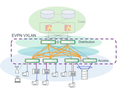
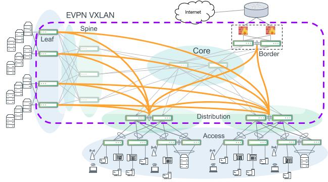
The design in the figure below prescribes for configuring a VTEP at every switch in the access and distribution layer. Both access layer and distribution layer switches must perform VXLAN encapsulation and decapsulation and support routing in and out of VXLAN tunnels.
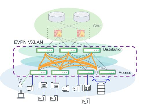
An example modern campus design. EVPN VXLAN provides VLAN extension and layer 2 connectivity across the campus. Distribution and access layer switches are both VTEPs and perform VXLAN encapsulation for the network.
In this design above, northbound links from the distribution layer switches are ideally discrete layer 3 routed links. Since MLAG is not required for the southbound access layer connectivity, the introduction of MLAG for strictly this purpose weakens some of the design’s inherent advantages. A design that requires connectivity using MLAG at the distribution layer limits the distribution layer to a strict pair of switches, increases control plane dependencies, and increases troubleshooting complexity.
A similar design as the previous figure with distribution layer switches configured with MLAG.
Platform choice in these designs is more rigid with the need for VXLAN encapsulation and VXLAN routing support. For access layer switches, Helix4 and Hurricane2-based platforms do not offer VXLAN support. As a result, we recommend Trident3 or Mellanox Spectrum-based platforms, which support VXLAN routing.
| Tier | Supported Platforms |
|---|---|
| Access | Broadcom Trident3, Trident II+ or Mellanox Spectrum-based platform. |
| Distribution | Broadcom Trident3, Trident II+ or Mellanox Spectrum-based platform is preferred. Broadcom Tomahawk family is acceptable, although routing in and out of VXLAN tunnels (RIOT) on Tomahawk platforms introduces a few limitations and extra configuration. |
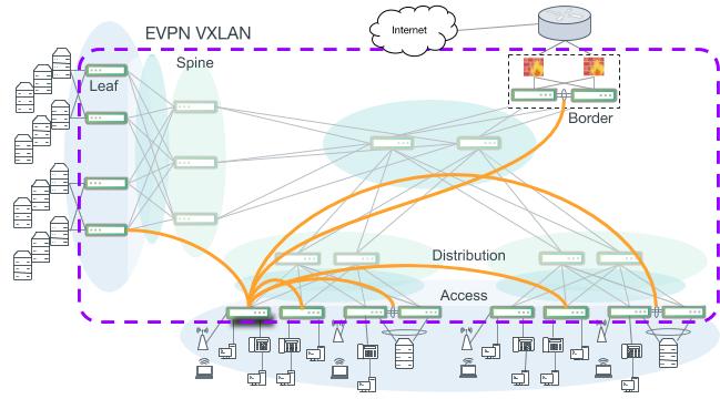
The non-MLAG design two figures above can be improved with the addition of dedicated border switches in the network segment. This option provides a number of significant benefits by removing complexity at the distribution layer switches. In contrast to the design above, the distribution layer switches do not need to serve as VTEPs for the network. VTEP switches are only in the access and border layers, which leaves the distribution layer to perform IP routing and delivering VXLAN packets between VTEPs.
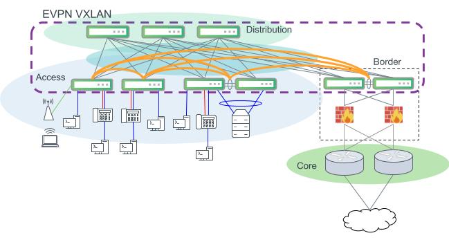
Layer 3 design using EVPN VXLAN. Access switches act as VTEPs and support VXLAN encapsulation. VLANs can be extended across the campus to other access switches across the routed distribution layer.
This design option also provides more flexibility for northbound access to the core or the rest of the campus network. Border switch segments can be designed more flexibly and may be implemented more easily as an MLAG pair to retain the inherent design benefits of a modern layer 3 network.
Platform choice in this design follows closely with other VXLAN options. Access and border switches must be able to support VXLAN encapsulation/decapsulation and also routing in and out of VXLAN tunnels (RIOT) to support symmetric mode. Helix4, Hurricane2 and other native 1Gbps switch ASICs do not offer VXLAN support. As a result, we recommend Trident3 or Mellanox Spectrum-based platforms, which support VXLAN routing. Distribution switches do not perform any VXLAN encapsulation/decapsulation in this design and have fewer feature driven requirements.
| Tier | Supported Platforms |
|---|---|
| Access | Any Broadcom Trident3, Trident II+ or Mellanox Spectrum-based platform. |
| Border | Any Broadcom Trident3, Trident II+ or Mellanox Spectrum-based platform is preferred. Broadcom Tomahawk family is acceptable, although routing in and out of VXLAN tunnels (RIOT) on Tomahawk platforms introduces a few limitations and extra configuration. |
Multiple Distribution Layers
The maximum size of a single access layer is bound by the number of ports on the distribution layer switches. For example, a 32 port distribution layer switch can interconnect 30 access layer switches, leaving two uplinks. To scale out access layer connectivity, more port dense distribution switches can be used, or an additional access aggregation block can be added. Designs built using layer 2 bonds for switch uplinks should limit the size of the access layer to avoid problems with spanning tree and layer 2 scaling as discussed in an earlier section.
When adding or designing for a more than two aggregation and access network segments, the addition of a dedicated core should be considered. As discussed earlier, a dedicated layer 3 core layer provides several advantages and, most importantly, reduces cable complexity for interconnections to other network blocks. A multi-building campus may not be able to connect all buildings and network segments to each other due to geographical and cabling challenges.
Multiple campus segments connected with a collapsed core design. Full link redundancy creates a mesh and does not scale.
Multiple campus segments interconnected with a dedicated core. A network segment only needs to connect to the core instead of every other segment.
A campus core layer can be easily built using BGP Unnumbered. In the design above, the distribution layer switches and core layer switches peer with each other using eBGP Unnumbered to manage IP addressing and also create the BGP neighbor relationships to exchange routes. With a Cumulus Linux data center or server room, all of the routed links included in the grey box in the figure above can be built and maintained using BGP Unnumbered. The WAN/edge devices can also run BGP and peer with the rest of the campus core.
The addition of a dedicated core layer with multiple interconnected campus network segments also introduces additional implementation options with EVPN and VXLAN. In the design in the figure above, layer 2 VLANs cannot be extended across the core layer. The access aggregation segment on bottom of the figure is a layer 2 access aggregation design, so VLANs can be natively trunked through the distribution layer to other access switches. Since a dedicated core layer is only layer 3, VLAN extension stops at this network segment and cannot cross the core.
EVPN and VXLAN is the solution to enable campus network designers to build a truly dedicated layer 3 core network and still provide VLAN and layer 2 extension to users and devices across the entire campus beyond what was traditionally possible.
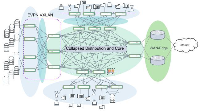
There are two main variations of a large scale EVPN VXLAN campus when there is a dedicated layer 3 campus core. The main difference being at which layer the VTEPs are implemented. A traditional layer 2 access and aggregation block can be constructed with layer 2 trunks and MLAG bonding, with VTEPs at the distribution layer. However, use caution to avoid creating large layer 2 domains, extended over large numbers of switches with this design.
NVIDIA does not recommend implementing VTEP functionality in the core layer. Core switches should only perform simple IP routing to more closely adhere to core layer design principles. This may require that a set of border switches be used to provide VXLAN encapsulation/decapsulation to other areas of the campus depending upon the particular needs and use cases.
An EVPN VXLAN-enabled campus with VTEPs at the distribution layer. Access switches use layer 2 bonds to an MLAG pair of distribution switches. Access VLANs can be extended through the core to other distribution access blocks or to an EVPN VXLAN-enabled data center.
This design increases platform flexibility and choice on access switches as they do not need to perform VXLAN encapsulation. Inside of a distribution-access segment, VLANs are extended and trunked using normal 802.1q VLAN tagging through the distribution layer. Routing for access VLANs occurs in the distribution layer. BGP Unnumbered is recommended to configure the layer 3 links to the core and also carry the EVPN address family to enable VXLAN. For performance and best scalability, symmetric mode with IRB (integrated routing and bridging), is the recommended inter-subnet routing strategy.
Symmetric mode with distributed anycast gateways provides for devices to move between access switches and always perform routing at the local switch. All routing for access VLANs occurs in the context of a tenant (VRF). The global routing table is used to carry and advertise routing information for the network endpoints (such as VTEP addresses and loopbacks). All IP subnets for access VLANs exist as a member of a VRF. More information about VRFs in this design is discussed below.
Data center network segments that implement VXLAN and EVPN can also be folded into the broader EVPN VXLAN-enabled campus. This provides opportunities to consolidate and centralize server and compute resources that had been traditionally co-located in the access or distribution layer. For more information about using EVPN and VXLAN in a data center network, visit our EVPN solution page.
Distribution layer or border switches serve as VTEPs; thus, they carry the most stringent platform requirements. Distribution layer switches must be able to support VXLAN encapsulation/decapsulation and also routing in and out of VXLAN tunnels (RIOT). Core switches do not serve as VTEPs and only perform IP routing to more closely adhere to core layer design principles.
| Tier | Supported Platforms |
|---|---|
| Distribution | Any Broadcom Trident3, Trident II+ or Mellanox Spectrum-based platform is preferred. Broadcom Tomahawk family is acceptable, although routing in and out of VXLAN tunnels (RIOT) on Tomahawk platforms introduces a few limitations and extra configuration. |
| Border | Any Broadcom Trident3, Trident II+ or Mellanox Spectrum-based platform is preferred. Broadcom Tomahawk family is acceptable, although routing in and out of VXLAN tunnels (RIOT) on Tomahawk platforms introduces a few limitations and extra configuration. |
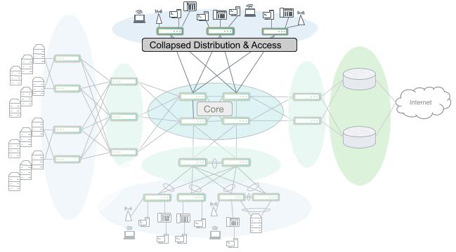
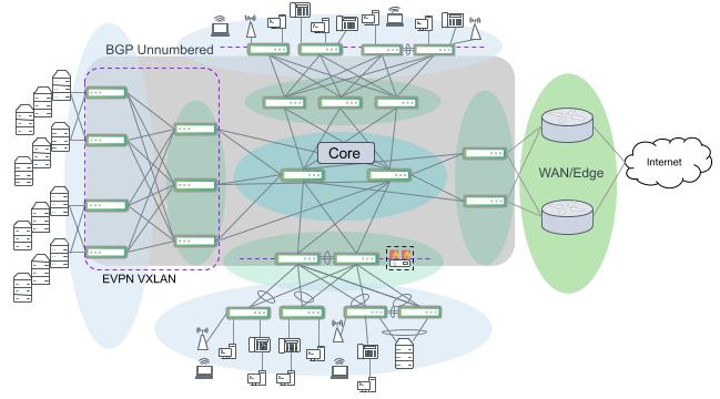
Another variation of a campus EVPN VXLAN design is a more modern and scalable network version that uses BGP Unnumbered through the core down to the access layer switches. Access layer switches are VTEPs and perform VXLAN encapsulation and decapsulation and also routing in and out of VXLAN tunnels (RIOT). For performance and best scalability, symmetric mode with IRB (integrated routing and bridging), is the recommended inter-subnet routing strategy.
A more scalable and robust EVPN VXLAN campus network. Not all VXLAN connections are indicated. Access switches serve as VTEPs leaving the distribution and core layers to perform only IP routing. BGP Unnumbered is used to build the core, distribution and access layers and also carries the EVPN address family to enable VXLAN across the entire campus.
Symmetric mode with distributed anycast gateways provides for devices to move between access switches and always route at the local switch. All routing for access VLANs occurs in the context of a tenant (VRF). The global routing table is used to carry and advertise routing information for the network endpoints (such as VTEP addresses and loopbacks). All IP subnets for access VLANs exist as a member of a VRF.
To provide the highest level of isolation and traffic control, VRFs can be implemented natively with EVPN to organize and classify IP subnets across the network. This is the concept of multi-tenancy. A VRF can be used to organize subnets across a layer 3 network similar to organizing devices by VLAN in flat layer 2 networks. VRFs are implemented as separate instances of a layer 3 routing table. Route lookups are performed only within a specific table, providing for isolation between layer 3 IP networks and even overlapping address space.
In the figure below, wireless devices and workstations are in different VLANs and different IP subnets, but are in the same VRF named “Data.” The VTEP access switch can route between subnets that are within the same VRF directly. For traffic between VRFs such as “Voice” and “Data”, there is no direct path due to VRF isolation. Packets must flow to a centralized location where VRF route leaking occurs or travels “out-and-back” through a VRF-unaware device. Notice in the figure below, inter-VRF traffic from the “Voice” VRF to the “Data” VRF must go through a centralized point and take a different path to get into the completely separate “data” IP network.
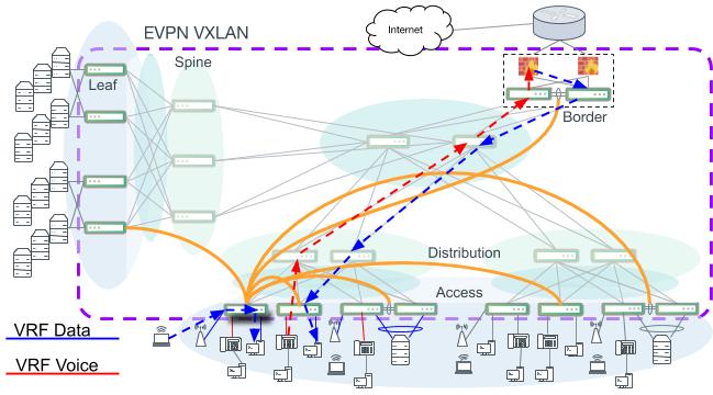
Intra-VRF and inter-VRF routing paths. Not all VXLAN tunnel connections are indicated.
Platform requirements in this example differ from the previous example when VTEPs are at the distribution layer. In this configuration, the access layer switch requirements now must include VXLAN capabilities, but the distribution layer switches do not. In this design, the distribution layer switches perform only IP routing and inherit the same simplicity and ease of use benefits as layer 3 core designs.
| Tier | Supported Platforms |
|---|---|
| Access | Any Broadcom Trident3, Trident II+ or Mellanox Spectrum-based platform. |
| Border | Any Broadcom Trident3, Trident II+ or Mellanox Spectrum-based platform. Broadcom Tomahawk family is acceptable, although routing in and out of VXLAN tunnels (RIOT) on Tomahawk platforms introduces a few limitations and extra configuration. |
Network Telemetry and Validation with Cumulus NetQ
Cumulus NetQ is a monitoring agent that delivers pertinent, real-time telemetry data for campus deployments of any size. As data is collected and processed by the telemetry server, Cumulus NetQ is able to provide a deep, rich set of network health status and validation checks.
For a single pane view, NetQ brings a modern graphical user interface. Important information such as network service health, IP addresses, MAC addresses, events and alarms are all pulled together into an easy to consume, browser-based view. A command line interface is also provided that can be used from any node that runs a NetQ agent. This provides access to any information, from any node, from anywhere an operator may be logged in.
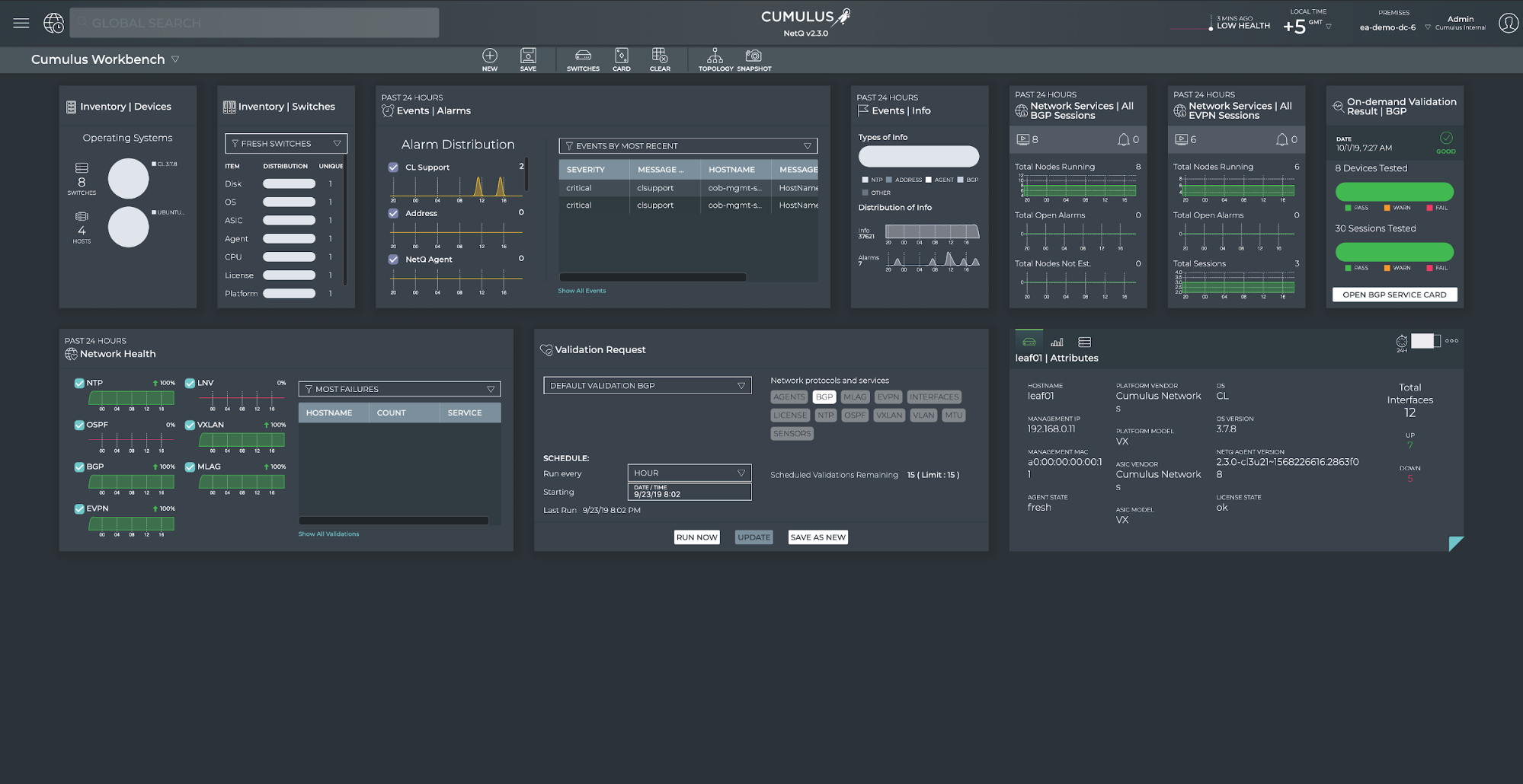
Cumulus NetQ GUI
NetQ also provides an API and structured data outputs to provide capabilities to integrate into nearly any 3rd party monitoring and alerting tools. Every NetQ CLI command has a JSON output option, which provides a structured response that is easy to parse and interpret programmatically. Cumulus NetQ also provides a full RESTful API with a standard OpenAPI definition that can be found in the API User Guide.
cumulus@oob-mgmt-server:~$ netq leaf01 show ip routes json
{
    "routes":[
        {
            "origin":"no",
            "lastChanged":1571689245.9370000362,
            "hostname":"leaf01",
            "prefix":"10.0.0.22/32",
            "vrf":"default",
            "nexthops":"169.254.0.1: swp52"
        },
        {
            "origin":"yes",
            "lastChanged":1571689245.9360001087,
            "hostname":"leaf01",
            "prefix":"10.0.0.11/32",
            "vrf":"default",
            "nexthops":"lo"
        },
        {
            "origin":"yes",
            "lastChanged":1571689245.9360001087,
            "hostname":"leaf01",
            "prefix":"10.2.4.1/32",
            "vrf":"vrf1",
            "nexthops":"vlan24-v0"
        },
        {
            "origin":"no",
            "lastChanged":1571689245.9360001087,
            "hostname":"leaf01",
            "prefix":"10.0.0.12/32",
            "vrf":"default",
            "nexthops":"169.254.1.2: peerlink.4094"
        },
        {
            "origin":"no",
            "lastChanged":1571689245.9360001087,
            "hostname":"leaf01",
            "prefix":"0.0.0.0/0",
            "vrf":"mgmt",
            "nexthops":"Blackhole"
        },

...
NetQ delivers advanced path tracing, even through a VXLAN overlay, by either layer 3 IP address or by layer 2 MAC address. NetQ agents stream forwarding information from every node, which provides a unique opportunity to perform a more complete path trace. A NetQ trace discovers all possible paths and checks each path, hop by hop for errors and possible problems. As shown in the example below, Cumulus NetQ CLI provides layer 2, layer 3 and VXLAN overlay trace capabilities.
cumulus@oob-mgmt-server:~$ netq trace 10.2.4.104 from server01 pretty Number of Paths: 8 Number of Paths with Errors: 0 Number of Paths with Warnings: 0 Path MTU: 1500 server01 bond0 -- swp1leaf02 vni: 104001 swp52 -- swp2 spine02 swp4 -- swp52 vni: 104001 leaf04 bond04 -- bond0 server04 swp52 -- swp2 spine02 swp3 -- swp52 vni: 104001 leaf03 bond04 -- bond0 server04 bond0 -- swp1 leaf02 vni: 104001 swp51 -- swp2 spine01 swp4 -- swp51 vni: 104001 leaf04 bond04 -- bond0 server04 swp51 -- swp2 spine01 swp3 -- swp51 vni: 104001 leaf03 bond04 -- bond0 server04 bond0 -- swp1 leaf01 vni: 104001 swp52 -- swp1 spine02 swp4 -- swp52 vni: 104001 leaf04 bond04 -- bond0 server04 swp52 -- swp1 spine02 swp3 -- swp52 vni: 104001 leaf03 bond04 -- bond0 server04 bond0 -- swp1 leaf01 vni: 104001 swp51 -- swp1 spine01 swp4 -- swp51 vni: 104001 leaf04 bond04 -- bond0 server04 swp51 -- swp1 spine01 swp3 -- swp51 vni: 104001 leaf03 bond04 -- bond0 server04
Fabric-wide service validations and health checks bring accurate alerting and diagnostics, and can provide prebuilt comprehensive testing for CI/CD automated workflows. NetQ agents stream a wide breadth of both control plane and data plane information that can be cross referenced and checked to better represent the status of the entire network instead of individual pieces. You can verify services like BGP, EVPN, MLAG and NTP as the total of all nodes working together in addition to physical interface settings, licenses, and environmental sensors.
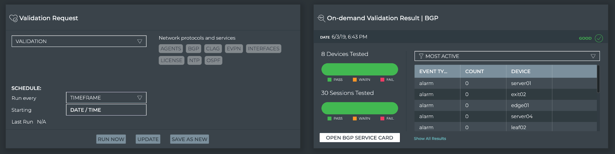
On-demand validation of a BGP fabric from the NetQ GUI
NetQ CLI Examples
netq show macs
cumulus@switch:~$ netq leaf01 show macs

Matching mac records:
Origin MAC Address        VLAN   Hostname          Egress Port          Remote Last Changed
------ ------------------ ------ ----------------- -------------------- ------ -------------------------
no     00:03:00:11:11:01  13     leaf01            bond01               no     Mon Oct 21 21:55:52 2019
no     00:03:00:22:22:01  24     leaf01            bond02               no     Mon Oct 21 21:55:52 2019
no     00:03:00:33:33:01  13     leaf01            vni13::10.0.0.134    yes    Mon Oct 21 21:55:52 2019
no     00:03:00:44:44:01  24     leaf01            vni24::10.0.0.134    yes    Mon Oct 21 21:55:52 2019
no     02:03:00:11:11:01  13     leaf01            bond01               no     Mon Oct 21 21:55:52 2019
no     02:03:00:11:11:02  13     leaf01            bond01               no     Mon Oct 21 21:55:51 2019
no     02:03:00:22:22:01  24     leaf01            bond02               no     Mon Oct 21 21:55:51 2019
no     02:03:00:22:22:02  24     leaf01            bond02               no     Mon Oct 21 21:55:51 2019
no     02:03:00:33:33:01  13     leaf01            vni13::10.0.0.134    yes    Mon Oct 21 21:55:52 2019
no     02:03:00:33:33:02  13     leaf01            vni13::10.0.0.134    yes    Mon Oct 21 21:55:51 2019
no     02:03:00:44:44:01  24     leaf01            vni24::10.0.0.134    yes    Mon Oct 21 21:55:52 2019
no     02:03:00:44:44:02  24     leaf01            vni24::10.0.0.134    yes    Mon Oct 21 21:55:51 2019
no     44:38:39:00:00:15  13     leaf01            peerlink             no     Mon Oct 21 21:55:51 2019
no     44:38:39:00:00:15  24     leaf01            peerlink             no     Mon Oct 21 21:55:51 2019
no     44:38:39:00:00:23  13     leaf01            vni13::10.0.0.134    yes    Mon Oct 21 21:55:52 2019
no     44:38:39:00:00:23  24     leaf01            vni24::10.0.0.134    yes    Mon Oct 21 21:55:52 2019
no     44:38:39:00:00:5c  13     leaf01            vni13::10.0.0.134    yes    Mon Oct 21 21:55:52 2019
no     44:38:39:00:00:5c  24     leaf01            vni24::10.0.0.134    yes    Mon Oct 21 21:55:52 2019
no     44:39:39:ff:40:95  4001   leaf01            vxlan4001::10.0.0.13 yes    Mon Oct 21 21:55:51 2019
                                                   4
no     c2:10:71:7d:82:de  4001   leaf01            vxlan4001::10.0.0.41 yes    Mon Oct 21 21:55:52 2019
no     f6:6b:a7:96:8c:b2  4001   leaf01            vxlan4001::10.0.0.42 yes    Mon Oct 21 21:55:51 2019
yes    44:38:39:00:00:03  13     leaf01            bridge               no     Mon Oct 21 21:55:52 2019
yes    44:38:39:00:00:03  24     leaf01            bridge               no     Mon Oct 21 21:55:52 2019
yes    44:38:39:00:00:03  4001   leaf01            bridge               no     Mon Oct 21 21:55:52 2019
yes    44:39:39:ff:00:13  13     leaf01            bridge               no     Mon Oct 21 21:55:52 2019
yes    44:39:39:ff:00:24  24     leaf01            bridge               no     Mon Oct 21 21:55:52 2019
yes    44:39:39:ff:40:94  4001   leaf01            bridge               no     Mon Oct 21 21:55:52 2019
netq show ip routes
cumulus@switch:~$ netq leaf01 show ip routes

Matching routes records:
Origin VRF             Prefix                         Hostname          Nexthops                            Last Changed
------ --------------- ------------------------------ ----------------- ----------------------------------- -------------------------
no     default         10.0.0.12/32                   leaf01            169.254.1.2: peerlink.4094          Mon Oct 21 20:20:45 2019
no     default         10.0.0.13/32                   leaf01            169.254.0.1: swp51,                 Mon Oct 21 20:20:45 2019
                                                                        169.254.0.1: swp52
no     default         10.0.0.134/32                  leaf01            169.254.0.1: swp51,                 Mon Oct 21 20:20:45 2019
                                                                        169.254.0.1: swp52
no     default         10.0.0.14/32                   leaf01            169.254.0.1: swp51,                 Mon Oct 21 20:20:45 2019
                                                                        169.254.0.1: swp52
no     default         10.0.0.21/32                   leaf01            169.254.0.1: swp51                  Mon Oct 21 20:20:45 2019
no     default         10.0.0.22/32                   leaf01            169.254.0.1: swp52                  Mon Oct 21 20:20:45 2019
no     default         10.0.0.41/32                   leaf01            169.254.0.1: swp51,                 Mon Oct 21 20:20:45 2019
                                                                        169.254.0.1: swp52
no     default         10.0.0.42/32                   leaf01            169.254.0.1: swp51,                 Mon Oct 21 20:20:45 2019
                                                                        169.254.0.1: swp52
no     mgmt            0.0.0.0/0                      leaf01            Blackhole                           Mon Oct 21 20:20:45 2019
no     vrf1            0.0.0.0/0                      leaf01            Blackhole                           Mon Oct 21 20:20:45 2019
no     vrf1            10.0.0.0/8                     leaf01            10.0.0.41: vlan4001,                Mon Oct 21 20:20:45 2019
                                                                        10.0.0.42: vlan4001
no     vrf1            10.0.0.253/32                  leaf01            10.0.0.41: vlan4001,                Mon Oct 21 20:20:45 2019
                                                                        10.0.0.42: vlan4001
no     vrf1            10.1.3.103/32                  leaf01            10.0.0.134: vlan4001                Mon Oct 21 20:20:45 2019
no     vrf1            10.2.4.104/32                  leaf01            10.0.0.134: vlan4001                Mon Oct 21 20:20:45 2019
yes    default         10.0.0.11/32                   leaf01            lo                                  Mon Oct 21 20:20:45 2019
yes    default         10.0.0.112/32                  leaf01            lo                                  Mon Oct 21 20:20:45 2019
yes    default         169.254.1.0/30                 leaf01            peerlink.4094                       Mon Oct 21 20:20:45 2019
yes    default         169.254.1.1/32                 leaf01            peerlink.4094                       Mon Oct 21 20:20:45 2019
yes    mgmt            192.168.0.0/24                 leaf01            eth0                                Mon Oct 21 20:20:45 2019
yes    mgmt            192.168.0.11/32                leaf01            eth0                                Mon Oct 21 20:20:45 2019
yes    vrf1            10.1.3.0/24                    leaf01            vlan13-v0                           Mon Oct 21 20:20:45 2019
yes    vrf1            10.1.3.1/32                    leaf01            vlan13-v0                           Mon Oct 21 20:20:45 2019
yes    vrf1            10.1.3.11/32                   leaf01            vlan13                              Mon Oct 21 20:20:45 2019
yes    vrf1            10.2.4.0/24                    leaf01            vlan24-v0                           Mon Oct 21 20:20:45 2019
yes    vrf1            10.2.4.1/32                    leaf01            vlan24-v0                           Mon Oct 21 20:20:45 2019
yes    vrf1            10.2.4.11/32                   leaf01            vlan24                              Mon Oct 21 20:20:45 2019
netq show ip address
cumulus@switch:~$ netq leaf01 show ip address

Matching address records:
Address                   Hostname          Interface                 VRF             Last Changed
------------------------- ----------------- ------------------------- --------------- -------------------------
10.0.0.11/32              leaf01            lo                        default         Mon Oct 21 20:20:45 2019
10.0.0.112/32             leaf01            lo                        default         Mon Oct 21 20:20:45 2019
10.1.3.1/24               leaf01            vlan13-v0                 vrf1            Mon Oct 21 20:20:45 2019
10.1.3.11/24              leaf01            vlan13                    vrf1            Mon Oct 21 20:20:45 2019
10.2.4.1/24               leaf01            vlan24-v0                 vrf1            Mon Oct 21 20:20:45 2019
10.2.4.11/24              leaf01            vlan24                    vrf1            Mon Oct 21 20:20:45 2019
169.254.1.1/30            leaf01            peerlink.4094             default         Mon Oct 21 20:20:45 2019
192.168.0.11/24           leaf01            eth0                      mgmt            Mon Oct 21 20:20:45 2019
netq check
The netq check command supports the ability to check bgp, evpn, clag, interfaces, license, mtu, ntp, ospf/ospf6, sensors, vlan and vxlan.
cumulus@oob-mgmt-server:~$ netq check sensors
Total Nodes: 13, Failed Nodes: 5, Checked Sensors: 136, Failed Sensors: 0
Hostname          Name            Description                         State      Value      Message
----------------- --------------- ----------------------------------- ---------- ---------- -----------------------------------
edge01            -               -                                   unknown    -          No sensor info present
server01          -               -                                   unknown    -          No sensor info present
server02          -               -                                   unknown    -          No sensor info present
server03          -               -                                   unknown    -          No sensor info present
server04          -               -                                   unknown    -          No sensor info present
netq trace
netq trace provides layer 2, layer 3 and VXLAN overlay support.
cumulus@oob-mgmt-server:~$ netq trace 10.2.4.104 from server01 pretty Number of Paths: 8 Number of Paths with Errors: 0 Number of Paths with Warnings: 0 Path MTU: 1500 server01 bond0 -- swp1leaf02 vni: 104001 swp52 -- swp2 spine02 swp4 -- swp52 vni: 104001 leaf04 bond04 -- bond0 server04 swp52 -- swp2 spine02 swp3 -- swp52 vni: 104001 leaf03 bond04 -- bond0 server04 bond0 -- swp1 leaf02 vni: 104001 swp51 -- swp2 spine01 swp4 -- swp51 vni: 104001 leaf04 bond04 -- bond0 server04 swp51 -- swp2 spine01 swp3 -- swp51 vni: 104001 leaf03 bond04 -- bond0 server04 bond0 -- swp1 leaf01 vni: 104001 swp52 -- swp1 spine02 swp4 -- swp52 vni: 104001 leaf04 bond04 -- bond0 server04 swp52 -- swp1 spine02 swp3 -- swp52 vni: 104001 leaf03 bond04 -- bond0 server04 bond0 -- swp1 leaf01 vni: 104001 swp51 -- swp1 spine01 swp4 -- swp51 vni: 104001 leaf04 bond04 -- bond0 server04 swp51 -- swp1 spine01 swp3 -- swp51 vni: 104001 leaf03 bond04 -- bond0 server04
Notes
-
You must build a design this large using layer 3 links. ↩︎